Part program generating device of surface texture measuring apparatus

a technology of surface texture and generating device, which is applied in the direction of programme control, total factory control, instruments, etc., can solve the problems of image measuring system not being able to perform an interference check automatically, image measuring system not being able to obtain information related to a three-dimensional shape of workpiece, etc., to prevent sensor displacement

Active Publication Date: 2017-09-21
MITUTOYO CORP
View PDF3 Cites 2 Cited by
  • Summary
  • Abstract
  • Description
  • Claims
  • Application Information

AI Technical Summary

Benefits of technology

[0018]In the present invention, preferably, the part program generator obtains coordinate values of the start point and coordinate values of the target point; obtains height data of the barrier, which is a projection or a step on the work piece and may prevent sensor displacement; configures a safety gap which should be secured between the sensor and the barrier when displacing the sensor above the barrier

Problems solved by technology

Therefore, when the part program is created by the off-line teaching using the two-dimensional CAD data, the image measuring system cannot obtain information related to a three-dimensional shape of the work piece.
Eve

Method used


Image

  • Part program generating device of surface texture measuring apparatus
  • Part program generating device of surface texture measuring apparatus
  • Part program generating device of surface texture measuring apparatus

Examples


first embodiment

[0055]FIG. 3 illustrates an overall configuration of an image measuring system 10 as a surface texture measuring apparatus. The image measuring system 10 includes an image measuring apparatus 1 and a control computer 2 drive controlling the image measuring apparatus 1 and executing required data processing.

[0056]The image measuring apparatus 1 is configured as follows. A measurement table 13 is mounted on a stage 11, and a work piece W (measured object) is placed on the measurement table 13. The measurement table 13 is driven in a Y-axis direction by a Y-axis drive mechanism (not shown in the drawings). An upwardly-extending frame 14 is fixated to a back end portion of the stage 11. An X-axis drive mechanism and a Z-axis drive mechanism (neither shown in the drawings) are provided on an interior of a cover 15 projecting on a front surface from a top portion of the frame 14. A CCD camera (hereafter referred to as a “camera”) 16 is supported by the X-axis drive mechanism and the Z-axi...

first modification

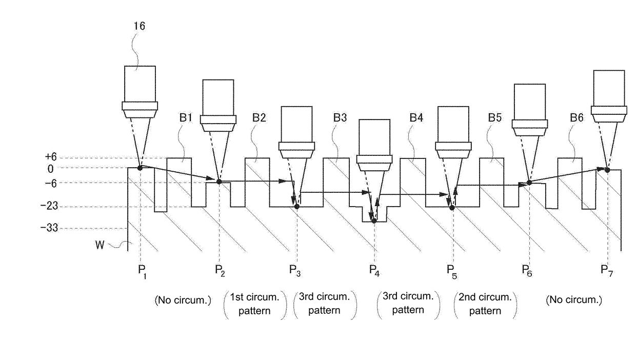
[0112]In the first embodiment above, the barrier height has to be entered for each circumvention move command. As a first modification, the input of the barrier height may not be requested every time. A method of doing this is considered in which the highest point of the work piece is entered in advance, for example. As shown in FIG. 20, for example, the highest point of the work piece is entered as one item in the parameter settings. In the process of the circumvention move command, the highest point of the work piece is the barrier height.

[0113]When the circumvention path is defined using the highest point of the work piece as the barrier height, it is obvious that the circumvention path is absolutely safe. The user does not have to enter the barrier height every time and therefore, the setting of measurement conditions becomes extremely simple. However, when creating the circumvention path in this way, the camera needs to be raised to the height safely overcoming the highest poin...

second modification

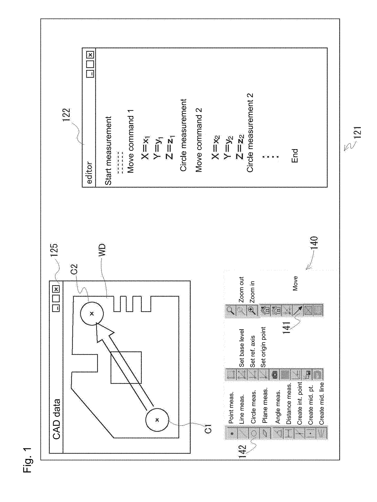
[0114]As a second method in which the input of the barrier height is not required every time, the height data, in addition to two-dimensional CAD data, is entered ahead of time in the host computer. In FIG. 21, a height distribution data memory 111 is attached to the CAD data memory 110. For example, in FIG. 22, the plan view of the work piece is displayed in the CAD data window 125 and distinctively tinted by hatching. The tinting is performed ahead of time by the user after reading the CAD data. In this example, the user designates each range and enters the height respectively. Using graphics processing of the host computer, for example, a height difference is displayed by changing density of the hatching based on the height. Of course, the display can also be distinguished using different colors. Alternatively, CAD data which is distinctively tinted ahead of time may be read. As a user aid, when a mouse cursor is positioned in each region inside the CAD data window 125, the defin...


PUM


Abstract

A part program generating device includes a CAD data memory storing CAD data of a work piece, a measurement condition definer receiving an input operation performed by a user and defining a measurement procedure, and a part program generator converting the measurement procedure defined by the measurement condition definer into a part program language. The measurement condition definer provides the user with, as a graphical user interface, an editing window capable of editing the measurement procedure in an editing language and a command icon providing a command to be used for defining the measurement procedure as an icon. The command icon includes a circumvention move command icon instructing to overcome a barrier when displacing a sensor from a start point to a target point.

Description

CROSS-REFERENCE TO RELATED APPLICATIONS[0001]The present application claims priority under 35 U.S.C. §119 of Japanese Application No. 2016-052043, filed on Mar. 16, 2016, the disclosure of which is expressly incorporated by reference herein in its entirety.BACKGROUND OF THE INVENTION[0002]1. Field of the Invention[0003]The present invention relates to a part program generating device of a surface texture measuring apparatus. Specifically, the present invention relates to a device supporting creation of a part program which commands a measuring apparatus to perform a work piece measurement procedure when measuring a measured object (hereafter referred to as a work piece) with a surface texture measuring apparatus.[0004]2. Description of Related Art[0005]Conventionally, in an image measuring apparatus of a CNC (Computer Numerical Control) type, a part program having descriptions of a measurement condition of a work piece has generally been created using the following two methods. A fi...

Claims


Application Information

Patent Timeline
IPC IPC(8): G06T7/60G06T7/40G06F3/0481G01B21/30G01B21/02
CPCG06T7/60G01B21/30G06T7/40G06F3/04817G01B21/02G01B11/24G01B21/04G01B11/2441G01B2210/50G05B19/4093G05B2219/37573Y02P90/02
Inventor KOGA, TETSUYAKOJIMA, TSUKASA
Owner MITUTOYO CORP
Why Eureka
Try Eureka