Power cable, power cable system, method of grounding power cable system and method of constructing power cable system
a technology of power cable and power cable system, which is applied in the direction of power cables, cables, insulated conductors, etc., can solve the problems of difficult to provide ecc along the power cable, and achieve the effect of ensuring safety
- Summary
- Abstract
- Description
- Claims
- Application Information
AI Technical Summary
Benefits of technology
Problems solved by technology
Method used
Image
Examples
first embodiment
(1) Power Cable System
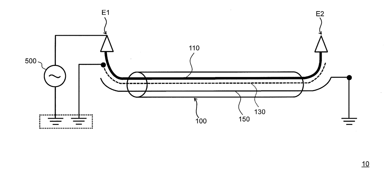
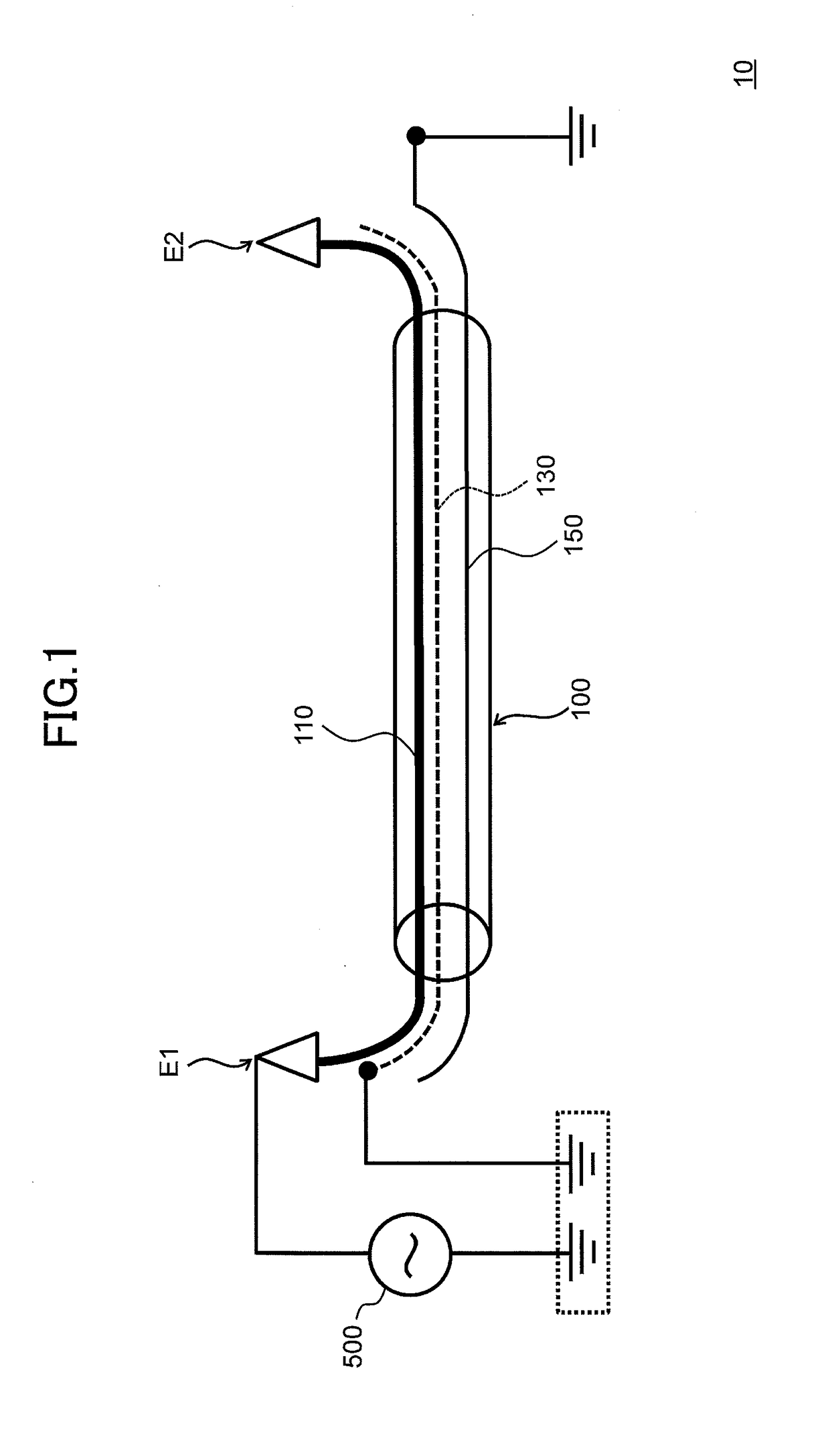
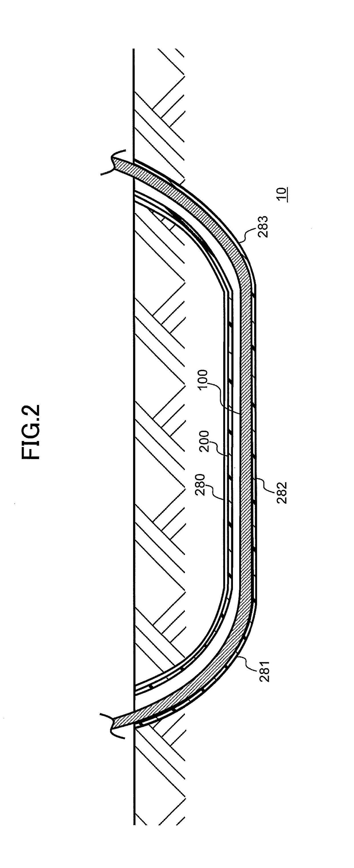
[0056]A power cable system of the embodiment is described with reference to FIG. 1 to FIG. 4. FIG. 1 is a schematic view illustrating a power cable system 10 of the embodiment. In FIG. 1, a single power cable 100 of three-phase power cables 100 is illustrated. FIG. 2 is a cross-sectional view of the power cable system 10 of the embodiment taken along an axial direction of a power cable 100. FIG. 3 is a cross-sectional view of the power cable system 10 of the embodiment taken along a direction that is perpendicular to the axial direction of the power cable 100. FIG. 4 is a cross-sectional view of the power cable 100 of the embodiment taken along the direction that is perpendicular to the axial direction.
[0057]Hereinafter, one end of the power cable 100 in the axial direction is referred to as “one end E1” and the other end of the power cable 100 in the axial direction is referred to as “the other end E2”. Similarly, one end of the inner shield layer 130 in the a...
first example
[0078]In the first example of FIG. 5, it is assumed that a ground fault occurs in the power cable 100 due to external force applied from an outer periphery of the power cable 100, due to an internal failure of an insulator 120 or the like, and the conductor 110 is short-circuited with the outer shield layer 150 via the inner shield layer 130 at a fault point AP. At this time, a fault current (FC) flows from the one end E1 side of the conductor 110, that is connected to the electric power substation 500, to the fault point AP. Here, as described above, the one end E1 of the inner shield layer 130 is directly grounded and the other end E2 of the inner shield layer 130 is open. Thus, the fault current does not flow to an earth ground at the other end E2 side of the inner shield layer 130, but flows to an earth ground at the one end E1 side of the inner shield layer 130 by returning at the fault point AP. As such, the fault current can be safely released to the earth ground at the one e...
second example
[0081]In the second example of FIG. 6, similar to the first example, it is assumed that a ground fault occurs in the power cable 100, and the conductor 110 is short-circuited with the outer shield layer 150 via the inner shield layer 130 at a fault point AP. At this time, the fault current (FC) flows from the other end E2 side of the conductor 110, that is connected to the electric power substation 500, to the fault point AP. Here, as described above, the other end E2 of the outer shield layer 150 is directly grounded and the one end E1 of the outer shield layer 150 is open. Thus, the fault current does not flow to an earth ground at the one end E1 side of the outer shield layer 150, but flows to an earth ground at the other end E2 side of the outer shield layer 150 by returning at the fault point AP. As such, the fault current can be safely released to the earth ground at the other end E2 side of the outer shield layer 150, in other words, to the earth ground at the electric power ...
PUM
| Property | Measurement | Unit |
|---|---|---|
| distance | aaaaa | aaaaa |
| distance | aaaaa | aaaaa |
| diameter | aaaaa | aaaaa |
Abstract
Description
Claims
Application Information
 - R&D
- Intellectual Property
- Life Sciences
- Materials
- Tech Scout
- Unparalleled Data Quality
- Higher Quality Content
- 60% Fewer Hallucinations
Browse by: Latest US Patents, China's latest patents, Technical Efficacy Thesaurus, Application Domain, Technology Topic, Popular Technical Reports.
© 2025 PatSnap. All rights reserved.Legal|Privacy policy|Modern Slavery Act Transparency Statement|Sitemap|About US| Contact US: help@patsnap.com


