
Structure of laser cleaning machine

a cleaning machine and laser technology, applied in the field of probe cards, can solve the problems of affecting the cleaning effect, and requiring more effort to remedy the problem, so as to achieve less satisfactory cleaning effect, deterioration of function or shape deformation

Inactive Publication Date: 2017-09-28
GIGA SOLUTION TECH
View PDF0 Cites 16 Cited by
  • Summary
  • Abstract
  • Description
  • Claims
  • Application Information

AI Technical Summary

Benefits of technology

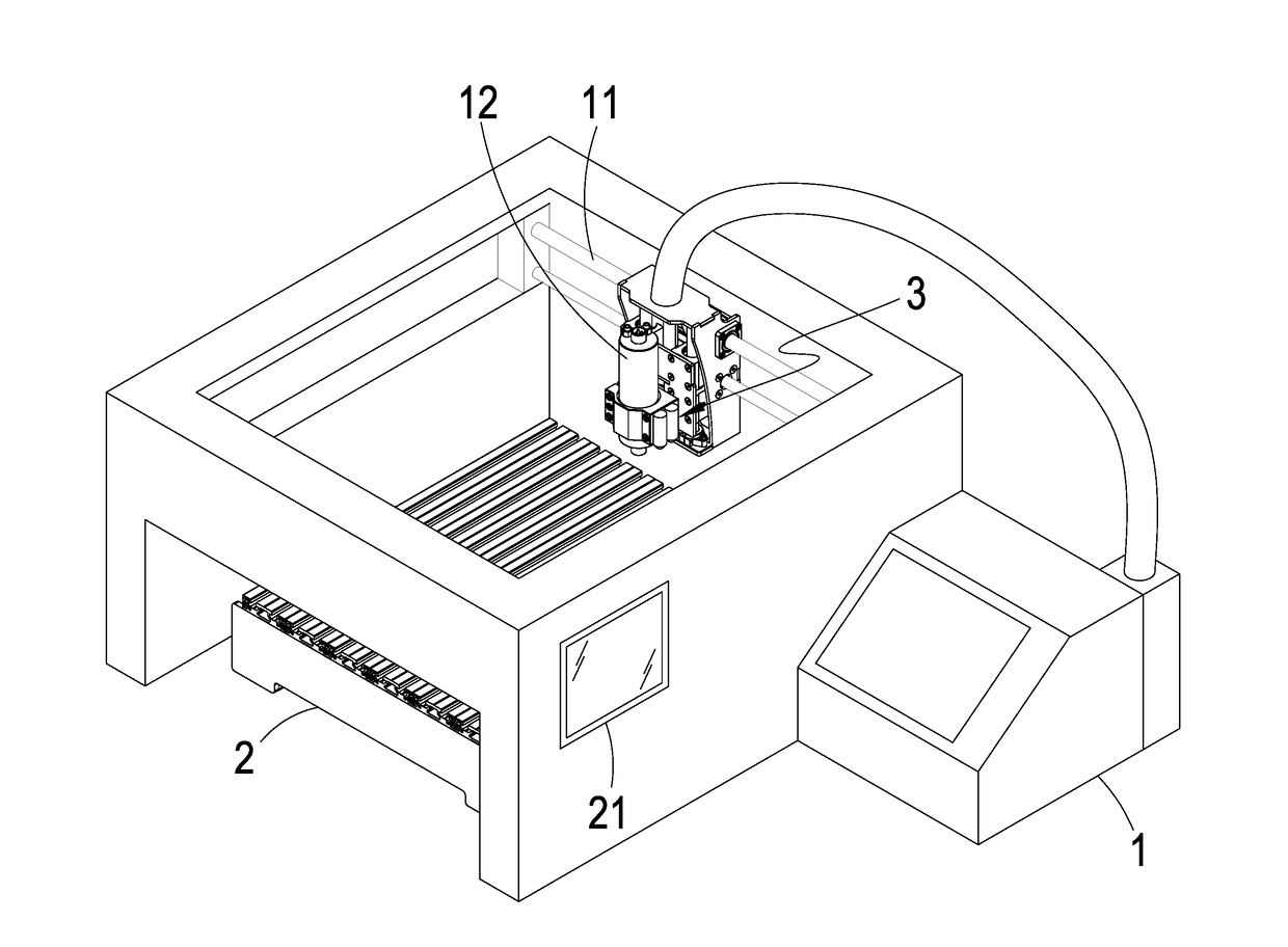
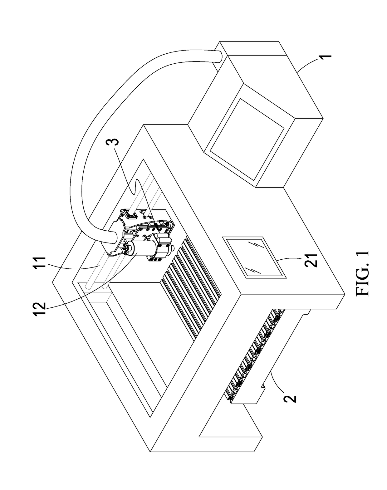
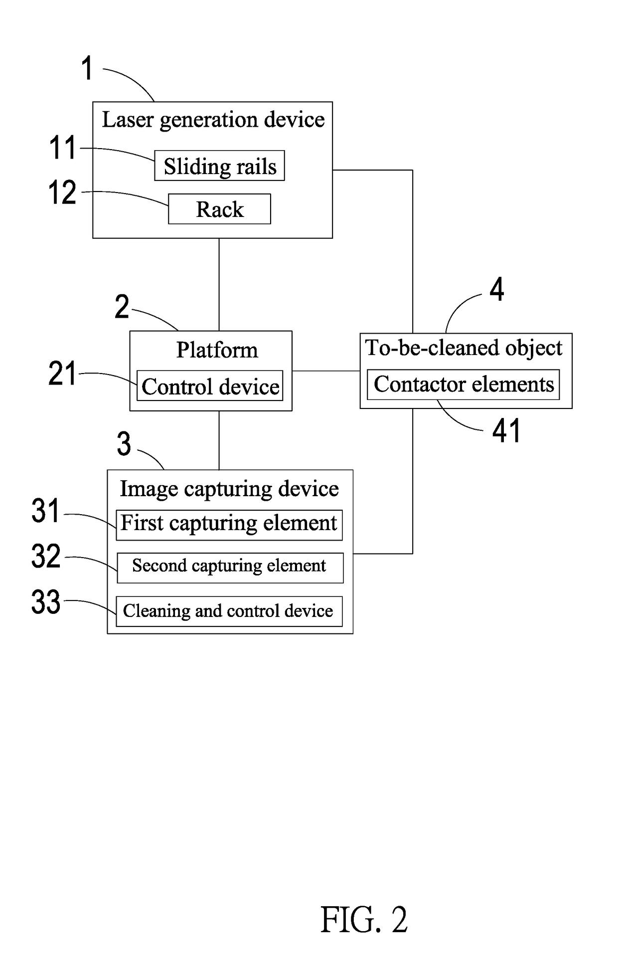
The present invention is a laser cleaning machine that uses a laser to enhance cleaning quality and efficiency. The machine has a laser generation device, a platform for supporting the object to be cleaned, an image capture device with two capturing elements, and a cleaning and control device. The image capture device obtains location information for the object, and the cleaning and control device determines an optimized path and instructs the laser generation device to conduct cleaning accordingly. The invention allows for quick and convenient location information determination and high-quality and highly efficient cleaning.

Problems solved by technology

However, as such, some aluminum or impurity would be attached to the contactors' tips as bumps and these bumps may damage the electrodes when the contactors touch the electrodes.
Additionally, some contactors may be missed during the cleaning process and more effort has to be spent to remedy this problem.
Firstly, the cleaning is inconvenient or the cleaning effect is less satisfactory.
In the worst case, some contactors may suffer deteriorated function or shape deformation.
Secondly, the cleaning process may miss some contactors, causing inferior cleaning efficiency.

Method used


Image

  • Structure of laser cleaning machine
  • Structure of laser cleaning machine
  • Structure of laser cleaning machine

Examples


Embodiment Construction

[0021]The following descriptions are exemplary embodiments only, and are not intended to limit the scope, applicability or configuration of the invention in any way. Rather, the following description provides a convenient illustration for implementing exemplary embodiments of the invention. Various changes to the described embodiments may be made in the function and arrangement of the elements described without departing from the scope of the invention as set forth in the appended claims.

[0022]As shown in FIGS. 1 and 2, a laser cleaning machine according to an embodiment of the present invention is for cleaning a to-be-cleaned object 4. In the present embodiment, the to-be-cleaned object 4 is a probe card having an array of contactor elements 41. The probe card can be of various types such as the cantilever probe card, the vertical probe card, the membrane probe card, the pogo probe card, the micro spring probe card, or the MEMS (Micro Electro Mechanical System) probe card.

[0023]The...


PUM

PropertyMeasurementUnit
AC charging voltageaaaaaaaaaa
wave lengthaaaaaaaaaa

Abstract

The structure of a laser cleaning machine contains a laser generation device for cleaning a to-be-cleaned object, a platform for supporting the to-be-cleaned object under a projection path of the laser generation device, an image capture device configured on the laser generation device, and a cleaning and control device inside the image capturing device for setting a traversal path of the laser generation device and for processing information obtained by the image capturing device. The image capturing device contains a first capturing element and a second capturing element to a side of the first capturing element. The cleaning and control device obtains the location distribution and the precise coordinate of each contactor element on the to-be-cleaned object, and then determines an optimized traversal path and instructs the laser generation device to conduct cleaning accordingly so as to achieves high-quality and highly efficient cleaning.

Description

BACKGROUND OF THE INVENTION[0001](a) Technical Field of the Invention[0002]The present invention is generally related to probe cards, and more particular to a structure of a laser cleaning machine of superior cleaning effect and efficiency.[0003](b) Description of the Prior Art[0004]In order to test a wafer, it is required to apply voltages or signals to the electrodes of the various integrated circuits on the wafer so as to drive the various integrated circuits. Therefore, a probe card having a large number of contactors for contacting the electrodes of the integrated circuits has to be prepared and utilized.[0005]In addition, to appropriately test the electrical characteristics of the integrated circuits, the insulating aluminum oxidation layers on the electrode surfaces have to be removed so that the contactors can reliably contact the electrodes with specific pressure. However, as such, some aluminum or impurity would be attached to the contactors' tips as bumps and these bumps ...

Claims


Application Information

Patent Timeline
Patent Type & Authority Applications(United States)
IPC IPC(8): G01R3/00B08B7/00
CPCB08B7/0042G01R3/00B23K26/0006B23K26/032B23K26/0876B23K37/0235B23K26/0622B23K26/352G01R1/07342
Inventor CHEN, LIANG-POCHIANG, SHANG-WEI
Owner GIGA SOLUTION TECH
Learn More