Image formation device

Active Publication Date: 2017-09-28
KONICA MINOLTA INC
View PDF2 Cites 6 Cited by
  • Summary
  • Abstract
  • Description
  • Claims
  • Application Information

AI Technical Summary

Benefits of technology

The present invention provides an image formation device that can efficiently discharge deteriorated toner without wasting paper when using continuous paper. The device includes an instruction for a method that controls the image formation section to print a first image on the continuous paper when the serial printing distance is equal to or shorter than a certain threshold. Additionally, if there is a large amount of deteriorated toner in the developer, the method decreases the proportion of deteriorated toner by printing a second image that differs from the first image. This results in a cleaner image and less waste of paper.

Problems solved by technology

It has been known that the toner is deteriorated when the toner has not been consumed for a long period of time, for example.
There is a problem that a decrease in the amount of charging of the toner and lowering of an image quality are caused due to toner deterioration.
However, in image formation on elongated continuous paper such as a paper roll, there is no region where, for example, the band-shaped pattern can be formed between adjacent images, and for this reason, there is a problem that the deteriorated toner cannot be discharged.
However, in, for example, the image formation device described in JP 5741656 B2, the following problem is caused.
As a result, a printing distance on the paper unnecessarily increases, leading to a problem that the paper is wastefully consumed.

Method used


Image

  • Image formation device
  • Image formation device
  • Image formation device

Examples


first embodiment

Configuration Example of Image Formation System 100

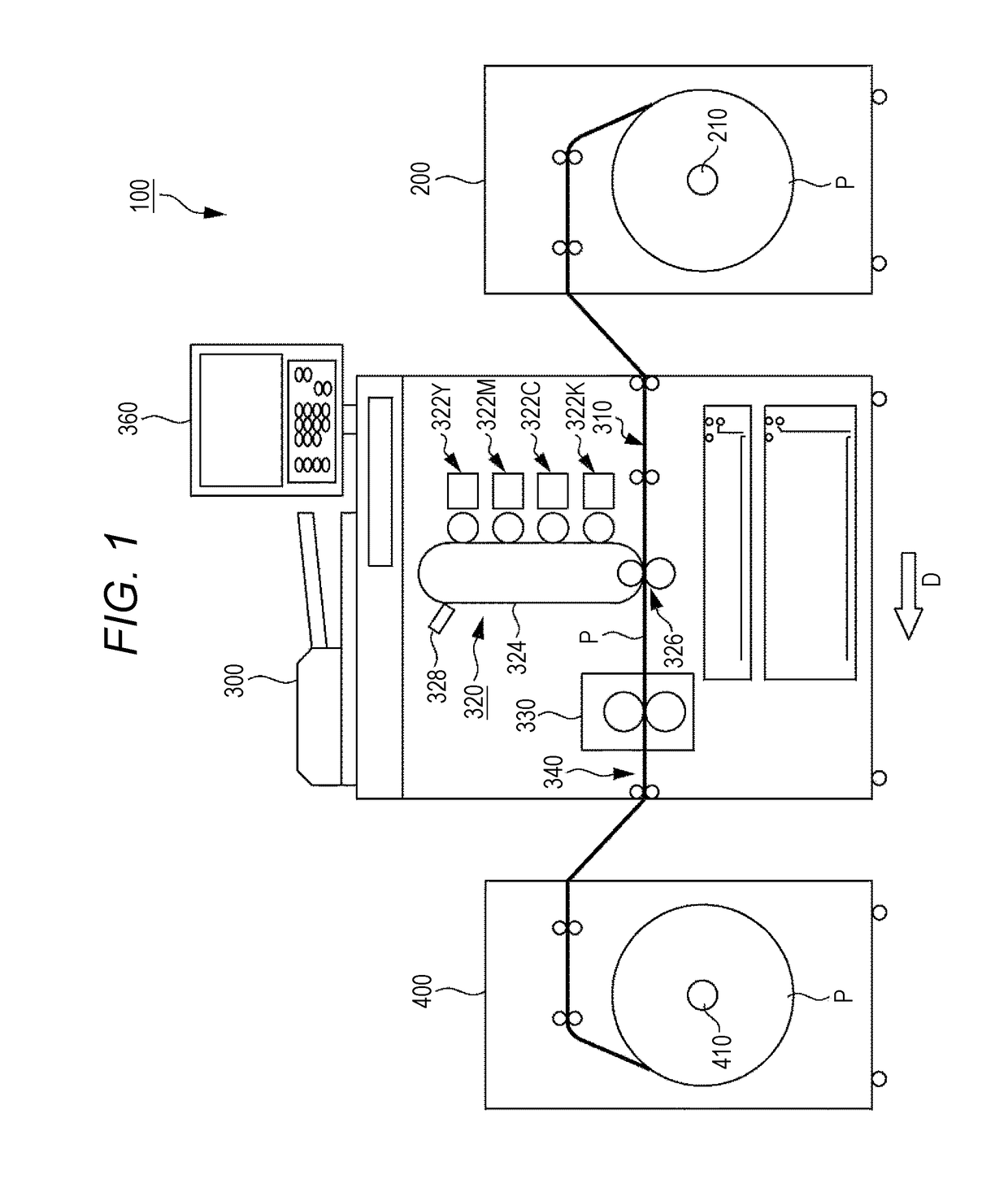
[0033]FIG. 1 illustrates an example of a schematic configuration of an image formation system 100 of an embodiment of the present invention. As illustrated in FIG. 1, the image formation system 100 is configured to form an image on continuous paper such as a paper roll P. The image formation system 100 includes a paper supply device 200, an image formation device 300, and a paper discharge device 400.

[0034]The paper supply device 200 is disposed on an upstream side of the image formation device 300 in a paper delivery direction D, and has a loading section 210 with a support shaft. The loading section 210 is configured to rotatably support the wound paper roll P to send out the paper roll P to the image formation device 300 based on the instruction of starting a job. The paper roll P is, for example, a label-printable paper roll, and includes a mount and a printing surface bonded via a seal member. Note that the continuous paper is ...

second embodiment

[0069]A second embodiment is different from the above-described first embodiment in that a user can select any of first and second discharge sequences when a serial printing distance L exceeds a second threshold Th2. Note that other configurations and functions of an image formation system 100 are similar to those of the above-described first embodiment. Thus, the same reference numerals are used to represent common components, and detailed description thereof will not be repeated.

Operation Example of Image Formation Device 300

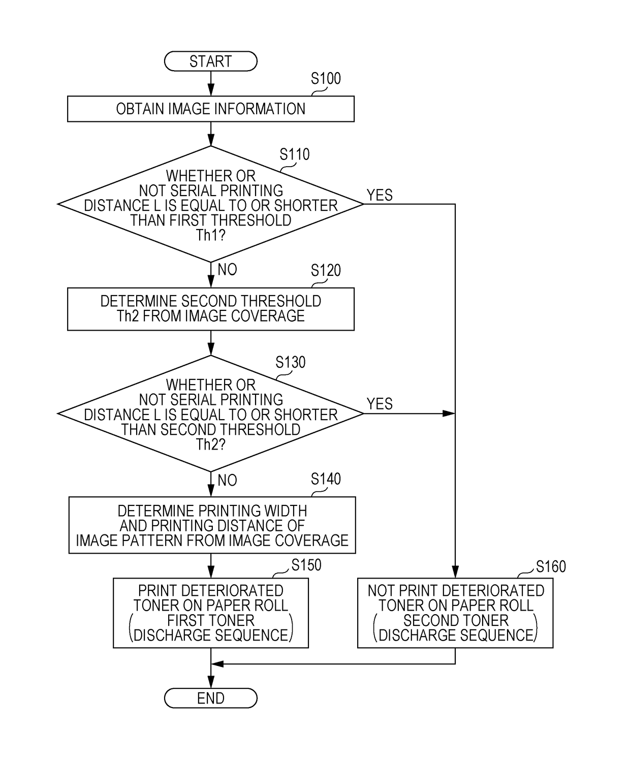
[0070]FIG. 8 is a flowchart of an example of operation of an image formation device 300 when deteriorated toner is discharged. A CPU 352 of the image formation device 300 executes software read from a ROM 354 to implement processing shown in the flowchart of FIG. 8. Note that processing of steps S200 to S230 and S250 to S270 is similar to the processing of the steps S100 to S160 of FIG. 4 described in the first embodiment, and therefore, detailed description t...


PUM


Abstract

An image formation device includes: an image formation section configured to develop, using toner, an electrostatic latent image formed on an image carrier based on job image information, thereby transferring a first image onto continuous paper; a hardware processor configured to determine whether or not a serial printing distance is equal to or shorter than a first threshold, wherein the serial printing distance is a distance at which the first image is printed on the continuous paper, and control the image formation section to print the first image on the continuous paper when the serial printing distance is equal to or shorter than a first threshold, and to decrease the proportion of deteriorated toner in a developer by printing the first image and a second image on the continuous paper when the serial printing distance exceeds a first threshold, wherein the second image is based on an image information.

Description

Cross Reference to Related Applications[0001]The entire disclosure of Japanese Patent Application No. 2016-060754 filed on Mar. 24, 2016 including description, claims, drawings, and abstract are incorporated herein by reference in its entirety.BACKGROUND OF THE INVENTIONField of the Invention[0002]The present invention relates to an image formation device.Description of the Related Art[0003]Typically, an image formation device employing an electrophotographic technique, such as a printer or a copying machine, has been broadly used. In the image formation device, image formation processing has been generally performed via the following series of process: a photosensitive drum having a uniformly-charged surface is irradiated with laser light by an optical device such that an electrostatic latent image is written on the photosensitive drum; and, after the electrostatic latent image has been developed using toner in a developer, the developed toner image is transferred onto paper via an...

Claims


Application Information

Patent Timeline
IPC IPC(8): G03G15/00
CPCG03G15/6529G03G15/0844G03G15/55G03G15/652G03G2215/00455G03G2215/0135
Inventor TOMINO, TOSHIAKI
Owner KONICA MINOLTA INC
Why Eureka
Try Eureka