
Tape dispensing tool

a technology for dispensing tools and tapes, applied in the direction of thin material handling, packaging, electrical equipment, etc., can solve the problems of manual wrapping not being efficient, quality control problems, and manual wrapping at an efficient rate and consistent amoun

Active Publication Date: 2017-09-28
TYCO ELECTRONICS LOGISTICS AG (CH)
View PDF9 Cites 3 Cited by
  • Summary
  • Abstract
  • Description
  • Claims
  • Application Information

AI Technical Summary

Benefits of technology

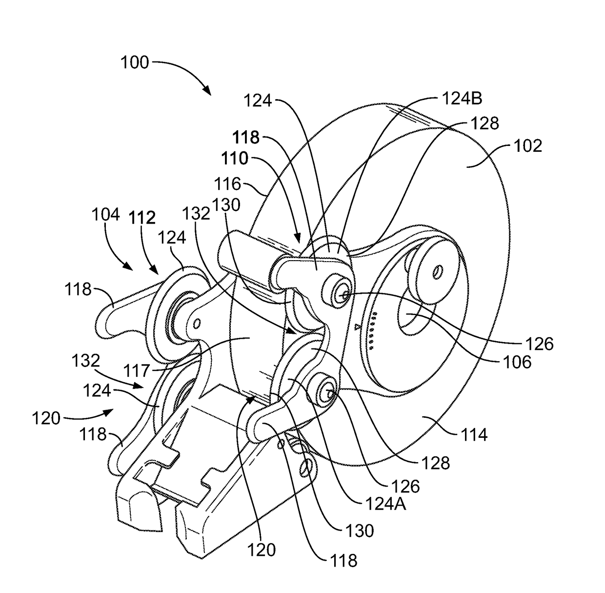
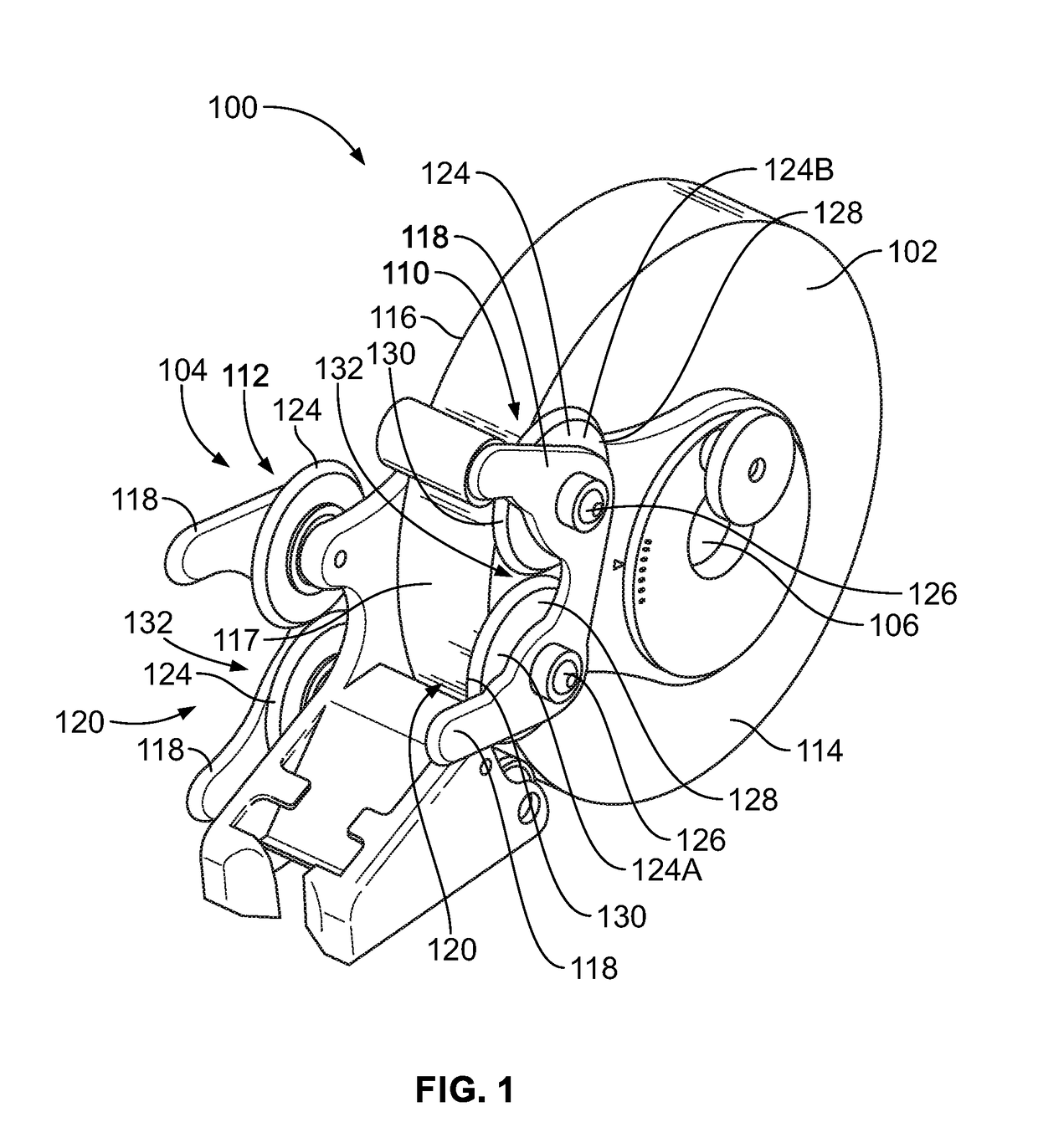
The patent describes two embodiments of a tape dispensing tool. The tool has a hub, fixed and adjustable holder arms. The fixed holder arm holds a cable bundle and the adjustable holder arm holds the cable bundle. The adjustable holder arm can be positioned to change the overlap of the tape when it is applied to the cable bundle. The technical effect of this patent is to provide a tool that makes it easier to apply tape to cable bundles and ensures a consistent and safe connection.

Problems solved by technology

For example, some complex manufactured products, such as automobiles, include many electrical wires and cables.
Manual wrapping is not without disadvantages, however, including quality control issues.
For example, manual wrapping at an efficient rate with a consistent amount of overlap during each revolution of the roll of tape is difficult and requires a significant learning curve.
Some automatic tape-wrapping tools have been developed to attempt to alleviate the quality control issues associated with manual wrapping, but the known automatic and manual-assist tools are not without disadvantages.
Such known automatic and manual-assist tools are expensive and not user-friendly.
For example, some such tools are heavy, have a cord that interferes with the operation, and / or vibrate during operation, which may be uncomfortable for the user.
In addition, some automatic tools put tension on the cable bundle as the tape is wrapped around the bundle, which may damage the electrical connections at the ends of the wires and / or cables in the bundle.

Method used


Image

  • Tape dispensing tool
  • Tape dispensing tool
  • Tape dispensing tool

Examples


Embodiment Construction

[0018]One or more embodiments described herein disclose a tape dispensing tool that assists a user wrapping tape around a bundle of electrical wires and / or cables. As used herein, the term “cable bundle” is used broadly to represent a group of multiple electrical wires and / or cables, including a wire harness. Thus, electrical wires and cables are used interchangeably. A cable bundle may also include optical conductors, such as fiber optic cables, in addition to or instead of electrical cables. Cable bundles may be used in automobiles and other transportation vehicles, industrial machinery, household appliances, and the like.

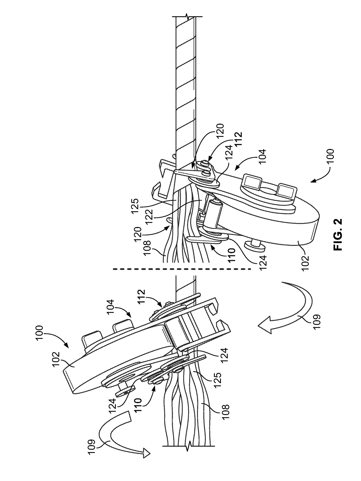
[0019]The tape dispensing tool is configured to be rotated around the bundle of wires and / or cables, such that the tape dispensing tool is moved around a perimeter of the bundle to helically apply tape to the bundle. The tape dispensing tool is configured to provide a consistent amount of overlap of the tape as the tool revolves around the bundle, thus improving ...


PUM

PropertyMeasurementUnit
anglesaaaaaaaaaa
anglesaaaaaaaaaa
anglesaaaaaaaaaa

Abstract

A tape dispensing tool includes a hub, a fixed holder arm, and an adjustable holder arm. The hub extends through a core of a roll of tape. The fixed holder arm extends from the hub along a first side of the roll of tape and has a fixed orientation relative to the hub. The fixed holder arm includes a first cradle configured to receive a cable bundle therein. The adjustable holder arm extends from the hub along an opposite, second side of the roll of tape. The adjustable holder arm includes a second cradle configured to receive the cable bundle therein. The adjustable holder arm has an adjustable position relative to the hub and the fixed holder arm to select an angular position of the second cradle relative to the first cradle for setting an overlap amount as the tape is applied to the cable bundle.

Description

CROSS-REFERENCE TO RELATED APPLICATIONS[0001]This application claims priority to U.S. Provisional Application No. 62 / 313,875, filed 28 Mar. 2016, which is incorporated by reference in its entirety.BACKGROUND OF THE INVENTION[0002]The subject matter herein relates generally to tape dispensing tools.[0003]In many manufacturing facilities, groups of bundles of electrical wires and / or cables are wrapped in a tape. The bundles are wrapped for various reasons, such as to organize a working space by tying all of the wires and / or cables in the bundle together and to provide abrasion resistance for the wires and / or cables in the bundle. For example, some complex manufactured products, such as automobiles, include many electrical wires and cables. Wrapping bundles of wires and / or cables in tape serves to organize and simplify routing of the wires and / or cables during the manufacturing process. Tape wrapping also protects the cable bundles during operation of the manufactured product, such as ...

Claims


Application Information

Patent Timeline
Patent Type & Authority Applications(United States)
IPC IPC(8): H01B13/012H01B13/22H01B13/00B65H35/00B65H37/00
CPCH01B13/01281B65H35/0026H01B13/22H01B13/0036B65H37/007B65B13/025B65B27/105H02G3/32
Inventor HOUSER, MATTHEW STEVENKERSTETTER, CHADWICK ALANKARRASCH, CHRISTOPHER JOHN
Owner TYCO ELECTRONICS LOGISTICS AG (CH)
Learn More