Methods and systems for electrochemical machining of articles formed by additive manufacturing

a technology of additive manufacturing and electrochemical machining, which is applied in the direction of additive manufacturing, process efficiency improvement, additive manufacturing apparatus, etc., can solve the problems of limiting the as-built surface roughness, affecting the quality of the finished product, so as to reduce the surface roughness, and reduce the cost of production.

Active Publication Date: 2020-12-10
HONEYWELL INT INC
View PDF0 Cites 1 Cited by
  • Summary
  • Abstract
  • Description
  • Claims
  • Application Information

AI Technical Summary

Benefits of technology

[0030]In some embodiments, the cathode tube 400 may be fitted with a plurality of annular, non-conductive spacers 428, as illustrated in FIG. 5. The non-conductive spacers 428 serve to ensure that the metallic cathode tube 400 never makes contact with the interior surface of the pipe 100. The non-conductive spacers 428 also serve to maintain a consistent distance of separation between the flexible cathode tube 400 and the interior surface of the pipe 100 so that a consistent amount of material removal occurs at all areas of the interior surface. The spacers 428 may have gaps or other shape irregularities in them so that circulation of the electrolyte is able to be maintained. Any number of spacers 428 may be used, and they may be positioned along the tube 400 as required for a given implementation. Furthermore, in some embodiments, the cathode tube 400 may be provided with a plurality of holes 426, as shown in FIG. 5. The holes 426 allow the electrolyte solution to flow therethrough under the pressure supplied by the pump, which causes agitation in the electrolyte solution within the interior of the pipe 100 near the interior surface. In effect, the holes allow for a “jet” of electrolyte solution to be directed at the interior surface of the pipe 100. This agitation results in a more efficient and even removal of material.
[0031]Thus, using the action of the pump and the holes 426, electrolyte solution is moved through the interior of the pipe 100 while current is applied to effect ECM of the interior surfaces of the pipe 100. As the electrolyte solution is pumped and agitated within the pipe 100, it makes contact with the interior surfaces of the pipe 100 to gradually effect the removal of some metallic material. As rough surfaces that extend outward will geometrically make more contact with the electrolyte solution than other portions of the interior surface, the rough surfaces will be removed more quickly, thus causing a reduction in surface roughness. The electrolyte solution then carries away any removed material as it is pumped out of the pipe 100, as indicated by arrows 410.
[0032]Accordingly, the present disclosure has provided methods to overcome the aforementioned challenges of ECM in the context of interior surfaces of AM-built articles that have bends or other confined geometries, such as pipes. The embodiments of the present disclosure utilize a flexible ECM cathode in the form of a metallic tube that is inserted throughout the articles, and whose shape is able to conform to the interior of the article. In this manner, the cathode is brought sufficiently-close to all of the interior surface of the article to effect complete ECM polishing in an efficient manner. Using a flexible cathode, bends, curves, and other difficult interior geometries may be adequately polished to achieve the desired reduction in surface roughness.

Problems solved by technology

However, the limitation of as-built surface roughness becomes a common problem for metal AM parts using PBF.
The as-built surface roughness of metal AM parts is about 300-500 micro-inches in many cases, and even worse on internal surfaces.
Although post-processing (sand blasting, machining, etc.) can improve the surface roughness, it is time consuming and does not work well for the internal surfaces.
However, ECM has proven difficult in the context of the internal surfaces of additively manufactured articles that have bends in their structure, such as pipes, due to the requirement that the cathode be inserted throughout the article in order to ensure sufficient action of the ECM process (polishing).

Method used


Image

  • Methods and systems for electrochemical machining of articles formed by additive manufacturing
  • Methods and systems for electrochemical machining of articles formed by additive manufacturing
  • Methods and systems for electrochemical machining of articles formed by additive manufacturing

Examples


Embodiment Construction

[0014]The following detailed description is merely exemplary in nature and is not intended to limit the invention or the application and uses of the invention. As used herein, the word “exemplary” means “serving as an example, instance, or illustration.” Thus, any embodiment described herein as “exemplary” is not necessarily to be construed as preferred or advantageous over other embodiments. All of the embodiments described herein are exemplary embodiments provided to enable persons skilled in the art to make or use the invention and not to limit the scope of the invention which is defined by the claims. Furthermore, there is no intention to be bound by any expressed or implied theory presented in the preceding technical field, background, brief summary, or the following detailed description.

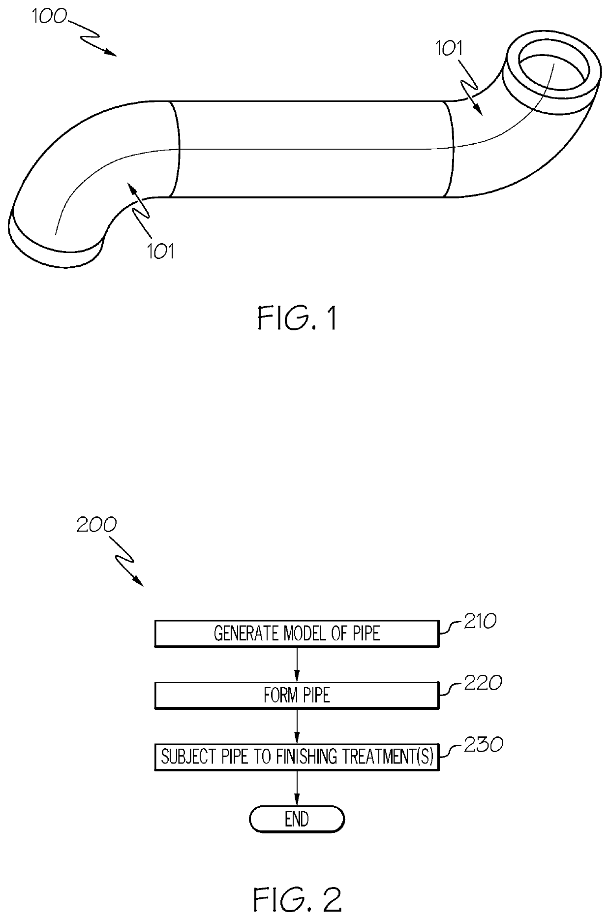
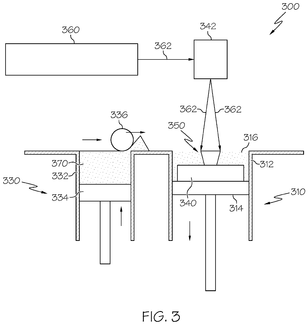
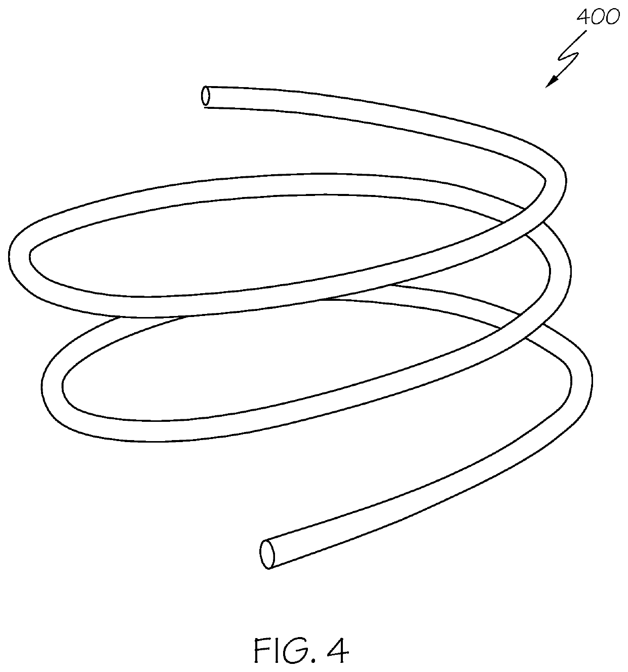
[0015]In order to overcome the aforementioned challenges of ECM in the context of interior surfaces of AM-built articles that have bends or other confined geometries, such as pipes, the embodim...


PUM

PropertyMeasurementUnit
poweraaaaaaaaaa
flexibleaaaaaaaaaa
voltageaaaaaaaaaa

Abstract

A method for electrochemical machining of a metallic article formed by additive manufacturing includes obtaining or producing the metallic article. The metallic article includes an interior surface and a geometry. The method further includes inserting a flexible, metallic cathode tube into the article. The metallic cathode is spaced apart from the interior surface of the article, and the metallic cathode tube is inserted so as to conform to the geometry of the article. Still further, the method includes introducing an electrolyte fluid into the metallic cathode tube and the interior surface of the article and electrochemical machining the metallic article by applying a voltage across the cathode tube and the metallic article, the metallic article functioning as an anode.

Description

TECHNICAL FIELD[0001]The present disclosure generally relates to methods and systems for manufacturing articles. More particularly, the present disclosure relates to methods and systems for electrochemical machining of articles formed by additive manufacturing.BACKGROUND[0002]Additive manufacturing (AM) is a manufacturing method that uses a three-dimensional model to directly fabricate an article layer by layer. One advantage of AM is the ability to realize complexity and design freedom, reduced weight, and rapid prototyping. In aerospace, automotive, and other industries, metal additive manufacturing, such as powder bed fusion (PBF) processes, are deployed on a wide basis. However, the limitation of as-built surface roughness becomes a common problem for metal AM parts using PBF. The as-built surface roughness of metal AM parts is about 300-500 micro-inches in many cases, and even worse on internal surfaces. In contrast, typical design requirements for maximum surface roughness may...

Claims


Application Information

Patent Timeline
Patent Type & Authority Applications(United States)
IPC IPC(8): C25F3/22B33Y80/00B33Y40/00
CPCC25F3/22B33Y40/00B33Y80/00B22F10/62B33Y40/20B22F2999/00Y02P10/25B22F2003/247
Inventor CAO, GANGMINYANG, SHANGYOULV, JINGKANGDOU, JUAN
Owner HONEYWELL INT INC
Why Eureka
Try Eureka