Display system and method

a display system and display technology, applied in the field of display systems, can solve the problems of reduced visibility behind the vehicle, reduced visibility, blind spots behind the vehicle, etc., and achieve the effect of expanding the full height of the composite imag

Active Publication Date: 2017-09-28
JAGUAR LAND ROVER LTD
View PDF4 Cites 59 Cited by
  • Summary
  • Abstract
  • Description
  • Claims
  • Application Information

AI Technical Summary

Benefits of technology

[0057]The first lateral image and / or the second lateral image can have a vertical height substantially equal to a vertical height of the second image. The lateral image data can extend the full height of the composite image.

Problems solved by technology

A particular problem encountered while towing is the reduced visibility behind the vehicle.
In particular, the trailer presents an obstacle which partially secures the driver's field of view behind the vehicle.
Large and small trailers typically reduce visibility and create a blind spot behind the vehicle.
The resulting lack of visibility can, for example, compromise the following manoeuvres: lane changes, overtaking, parking, joining a motorway (highway) and pulling out of junctions.
However, towing mirrors have several disadvantages, notably they increase the vehicle width and may reduce manoeuvrability in confined spaces.
Moreover, towing mirrors are not well suited to providing a view of other vehicles positioned directly behind the trailer.
Towing mirrors can also suffer from vibration and hence blurring of the image.
However, when a trailer is being towed behind the vehicle, the image generated by the rear-facing camera will be at least partially obscured.

Method used


Image

  • Display system and method
  • Display system and method
  • Display system and method

Examples


Embodiment Construction

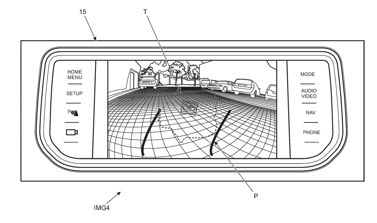
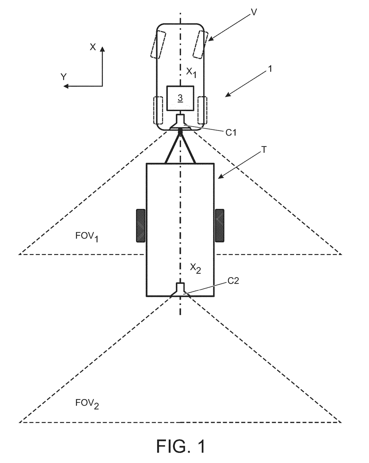
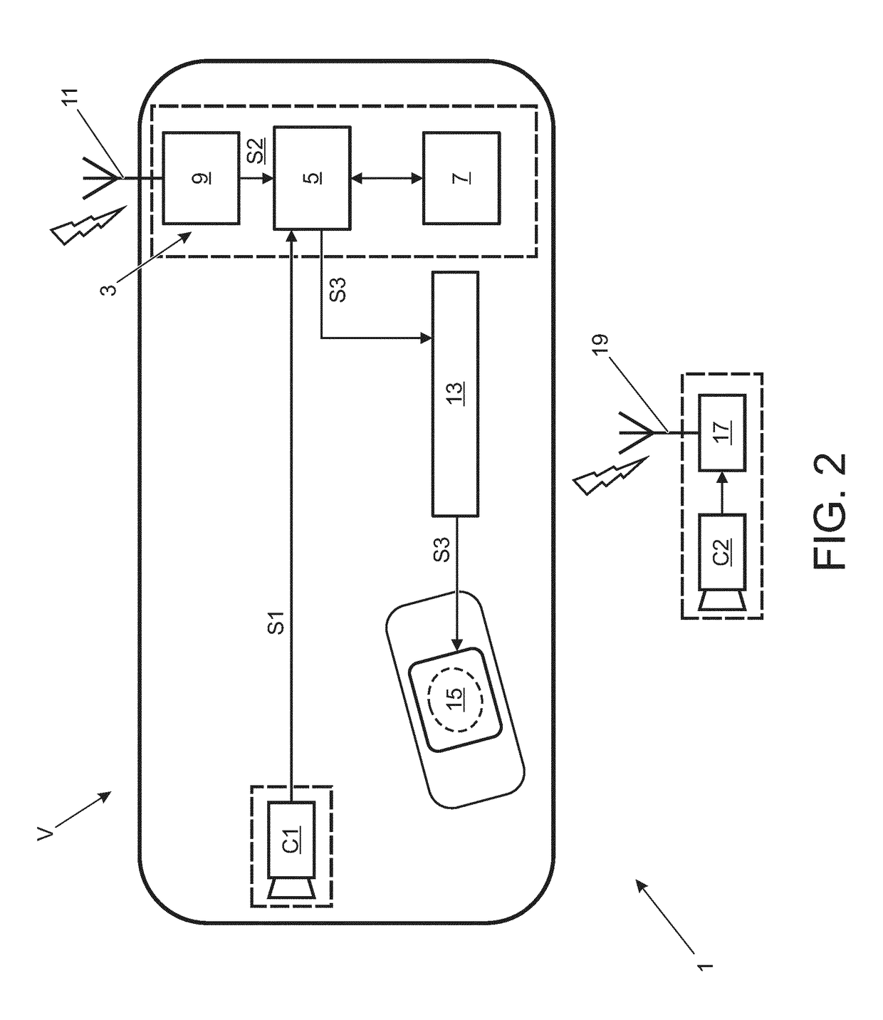
[0090]A rear-view display system 1 in accordance with an embodiment of the present invention will now be described with reference to the accompanying figures. The rear-view display system 1 is intended for use in a vehicle V towing a trailer T (referred to in combination as a rig) to generate a composite image for providing improved visibility for the vehicle driver of the region behind the vehicle V. The vehicle V in the present embodiment is an automobile or a utility vehicle. However, it will be appreciated that the rear-view display system 1 may be incorporated into other types of vehicle, such as a tractor unit.

[0091]The vehicle V has a first longitudinal axis X1, and the trailer T has a second longitudinal axis X2, as shown in FIG. 1. The terms “front” and “rear” are used herein in their conventional sense when defining the relative position of features on the vehicle V and the trailer T. The terms “rear-facing” and “rear-view” are used herein to refer to a position or orienta...


PUM


Abstract

The present disclosure relates to a display system (1) for generating a composite view of a region behind a vehicle (V) towing a trailer (T). A first camera (C1) is provided for outputting first image data corresponding to a first image (IMG1), the first camera (C1) being configured to be mounted in a rear-facing orientation to the vehicle (V). A second camera (C2) is provided for outputting second image data corresponding to a second image (IMG2), the second camera (C2) being configured to be mounted in a rear-facing orientation to the trailer (T). An image processor (5) receives the first image data and said second image data. The image processor (5) is configured to combine said first image data and said second image data to generate composite image data corresponding to a composite image (IMG3). The present disclosure also relates to a corresponding method of generating a composite image (IMG3), and to a rig made up of a vehicle (V) and a trailer (T).

Description

TECHNICAL FIELD[0001]The present disclosure relates to a display system for a vehicle towing a trailer, to a method of generating a composite image, and to a rig comprising a vehicle and a trailer.BACKGROUND[0002]It is common practice to tow a trailer behind a vehicle. A particular problem encountered while towing is the reduced visibility behind the vehicle. In particular, the trailer presents an obstacle which partially secures the driver's field of view behind the vehicle. Large and small trailers typically reduce visibility and create a blind spot behind the vehicle. The resulting lack of visibility can, for example, compromise the following manoeuvres: lane changes, overtaking, parking, joining a motorway (highway) and pulling out of junctions.[0003]In order to mitigate the aforementioned problems, it is common practice to fit a so-called towing mirror to the side mirrors of the vehicle. The towing mirrors extend laterally outwardly to provide improved visibility along the side...

Claims


Application Information

Patent Timeline
Patent Type & Authority Applications(United States)
IPC IPC(8): H04N5/445H04N7/18B60R1/00H04N5/232
CPCH04N5/44504H04N5/23293H04N7/181B60R1/00B60R2300/806B60R2300/406B60R2300/105B60R2300/8066B60R2300/303H04N23/633B60R2300/305H04N5/265G06T11/00H04N23/698H04N23/90G06T3/40B60R2001/1253
Inventor GREENWOOD, JEREMYSTRANO, GIOVANNI
Owner JAGUAR LAND ROVER LTD
Why Eureka
Try Eureka