Exoskeleton Device and Method of Impeding Relative Movement in the Exoskeleton Device

a technology of exoskeleton and relative movement, which is applied in the field of exoskeleton device and relative movement impedance in the exoskeleton device, can solve the problems of knee being completely locked, human legs not having continuous motion,

Active Publication Date: 2017-10-05
EKSO BIONICS
View PDF2 Cites 4 Cited by
  • Summary
  • Abstract
  • Description
  • Claims
  • Application Information

AI Technical Summary

Benefits of technology

[0004]It is an object of the present invention to provide a device and method that allows for a person to limit or obstruct the rate of movement about the knee and or hip joint of the leg(s) of that person and, specifically, to allow the person to limit

Problems solved by technology

Rotary brakes make sense in wheeled applications, but human legs do not have continuous motion.
A rotary brake will always apply the same braking force for the same force input on the handle at all angles of the brake, which may be disadvantageous in the case of a human exoskeleton.
As a result, a person trying to control the motion with the brake would find that even the slightest force on the handle wo

Method used


Image

  • Exoskeleton Device and Method of Impeding Relative Movement in the Exoskeleton Device
  • Exoskeleton Device and Method of Impeding Relative Movement in the Exoskeleton Device
  • Exoskeleton Device and Method of Impeding Relative Movement in the Exoskeleton Device

Examples


first embodiment

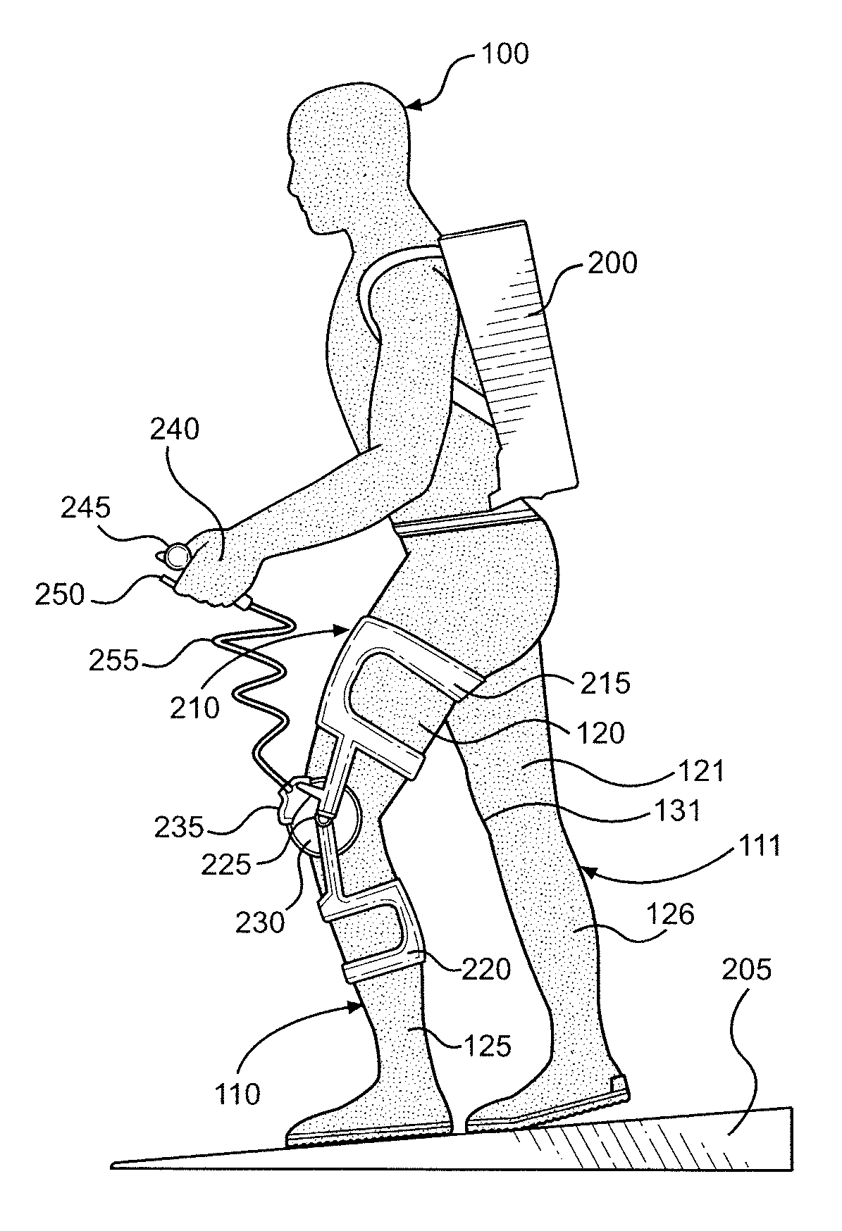
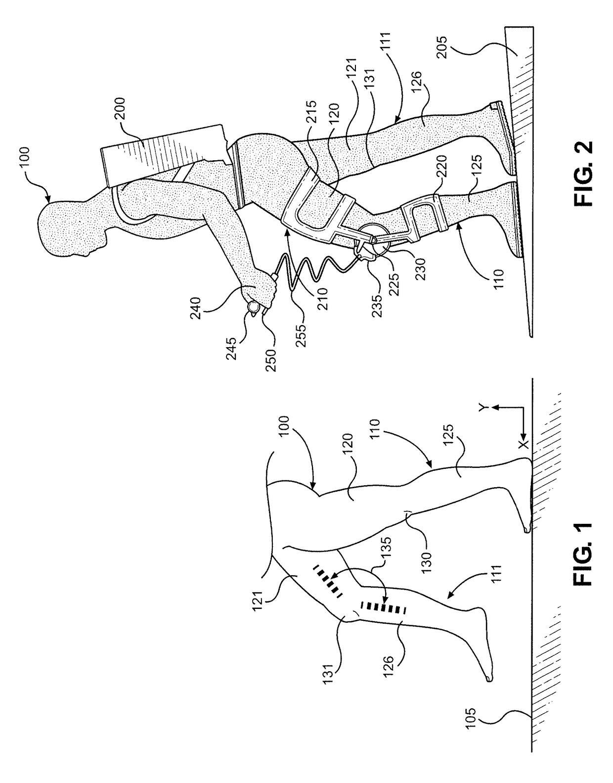
[0024]With reference now to FIG. 2, the present invention is illustrated. Person 100, wearing a backpack 200, is walking downhill on a surface 205. An exoskeleton device 210 is fitted to leg 110 of person 100. A thigh brace 215 of exoskeleton device 210 is coupled to upper leg 120 of person 100, and shank brace 220 of exoskeleton device 210 is coupled to lower leg 125 of person 100. Exoskeleton device 210 rotates at an exoskeleton knee joint 225, which is collocated with knee 130 of leg 110. A rotor 230 is attached to shank brace 220 and rotates about exoskeleton knee joint 225. The rotation of rotor 230 and exoskeleton knee joint 225 is limited by the action of a caliper 235. Caliper 235 is attached to thigh brace 215, with caliper 235 in close proximity to and selectively interacting with rotor 230. Person 100 controls the action of caliper 235 by using a hand 240 to squeeze a handbrake body 245 and a handbrake lever 250 to transmit a force through a brake line 255 to caliper 235....

second embodiment

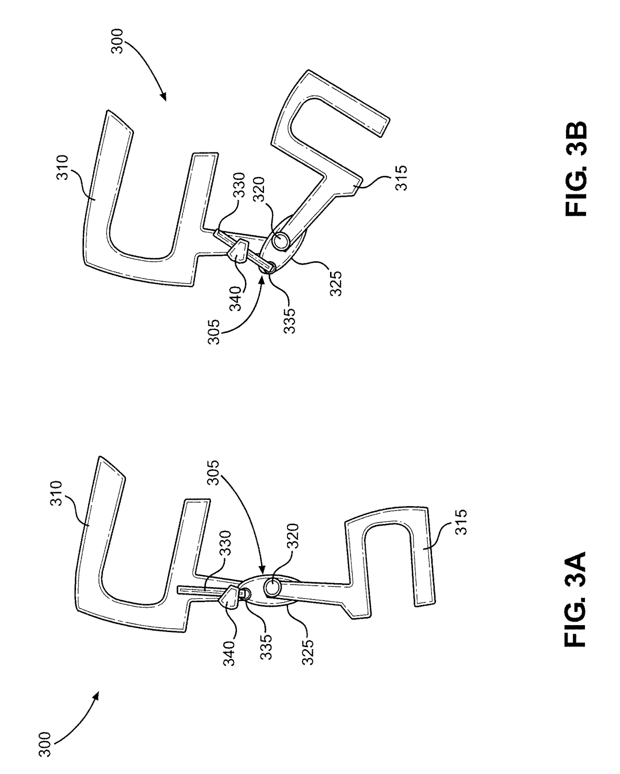
[0027]Turning to FIGS. 3A and 3B, the present invention is illustrated. FIG. 3A shows an exoskeleton device 300, equipped with a linear braking device 305, in a fully extended knee position, and FIG. 3B shows exoskeleton device 300 in a flexed knee position. As with exoskeleton device 210, exoskeleton device 300 is comprised of a thigh brace 310 that is rotatably connected to a shank brace 315 at an exoskeleton knee joint 320. Shank brace 315 is connected to a shank extension 325, and a linear brake shoe 330 is connected to shank extension 325 by a pivot joint 335. Linear brake shoe 330 passes through and in close proximity with a caliper 340. Caliper 340 is connected to thigh brace 310 and selectively interacts with linear brake shoe 330. Specifically, the person wearing exoskeleton device 300 controls the action of caliper 340 by using a handbrake or other device, as discussed above in connection with FIG. 2. As caliper 340 engages, or contacts, linear brake shoe 330, the rotation...

fourth embodiment

[0031]With reference now to FIG. 5A, the present invention is illustrated. Person 100, who is wearing backpack 200, is walking downhill on surface 205. The downward force exerted by the weight of backpack 200 is represented by dotted arrow 400. An exoskeleton device 500 is fitted to legs 110 and 111 of person 100 although, for simplicity, only the portion of exoskeleton device 500 fitted to leg 110 is described below. A thigh brace 505 of exoskeleton device 500 is coupled to upper leg 120 of person 100, and thigh link 510 is connected to thigh brace 505. Thigh link 510 is rotatably connected to an exoskeleton hip joint 515, with exoskeleton hip joint 515 rotatably connected to a hip-backpack connection 520. Hip-backpack connection 520 is coupled to belt 425 of backpack 200 at a thigh-backpack connection 525 on hip 435 of person 100. Thigh brace 505 of exoskeleton device 500 is rotatably coupled to an exoskeleton knee joint 530, and exoskeleton knee joint 530 is also rotatably couple...


PUM


Abstract

An exoskeleton device includes a first brace coupled to a first portion of a wearer of the exoskeleton device and a second brace coupled to a second portion of the wearer. A first joint connects the first and second braces and allows relative movement between the first and second braces. A first brake is controllable between an unactuated state and a plurality of actuated states, and the first brake impedes relative movement between the first and second braces at the first joint while the first brake is in one of the plurality of actuated states. A manual actuator is selectively used by the wearer during relative movement between the first and second braces. Use of the actuator causes the first brake to enter one of the plurality of actuated states such that relative movement between the first and second braces is impeded at the first joint.

Description

CROSS REFERENCE TO RELATED APPLICATIONS[0001]This application claims the benefit of U.S. Provisional Patent Application Ser. No. 62 / 046,545, which was filed on Sep. 5, 2014 and titled “Unpowered Exoskeletal Orthoses for Load Sharing Applications”. The entire content of this application is incorporated by reference.FIELD OF THE INVENTION[0002]The present invention relates to a devices and methods that augment a user's carrying capacity and / or aid in the prevention of injury during the performance of certain motions or tasks. More particularly, the present invention relates to devices and methods suitable for use by a person engaging in walking or descending while bearing weight. These devices include a set of artificial limbs that potentiate improved function of the person's appendages for activities including, but not limited to, walking while bearing weight with greater endurance and / or decreased risk of injury or allowing for more weight to be supported while walking.BACKGROUND OF...

Claims


Application Information

Patent Timeline
IPC IPC(8): A61F5/01
CPCA61F5/0102A61F2005/0158A61F2005/0167A61F5/0123
Inventor ANGOLD, RUSSAMUNDSON, KURT
Owner EKSO BIONICS
Why Eureka
Try Eureka