Cervical traction device and method of using same

a cervical traction and traction device technology, applied in the field of cervical traction, can solve the problems of inability to achieve a proper effect on the spine, decreased patient compliance with the treatment program, and inability to treat patients, so as to achieve the effect of reducing the storage space required and being more efficient in travel and transportation

Inactive Publication Date: 2017-10-12
SAVAGE ELTON DEVIN
View PDF5 Cites 2 Cited by
  • Summary
  • Abstract
  • Description
  • Claims
  • Application Information

AI Technical Summary

Benefits of technology

[0010]The skull attachments may be fixed to the frame, or they may be releasably attached, and may exist as a plurality of attachments to vary the positon of the user attachments relative to the frame. A plurality of suspension points (110) may help attach a device external to the frame (100) such as a source of cervical traction. The plurality of suspension points (110) may be arranged in a front-to-back manner, thereby allowing the angle at which traction is applied to the cervical vertebrae to be adjusted and varied.
[0013]The frame may be formed of two or more reversibly joined sections that may be disassembled. The frame may also be fabricated in a geometric shape that is substantially planar. Such a planar shape would minimize the storage space required by the frame and make it more efficient for travel and transport.

Problems solved by technology

A problem with conventional static, extension traction methods is that they often do not achieve a proper effect on the spine within an acceptable time frame.
For example, because the traction force applied during treatment is limited by the patient's tolerance level, proper treatment may require many repeated traction sessions in order to achieve the desired treatment outcome.
This is a problem because the scheduling and coordinating of multiple sessions can be inconvenient for many patients, and also patient compliance with the treatment program may decrease when numerous sessions are involved.
Also, the patients may continue to suffer from unacceptable levels of pain until the multiple required traction sessions have been completed.
Yet another problem with conventional static extension traction methods is that most patients experience discomfort during prolonged static traction sessions due to the constant and unchanging tension exerted in the spine.
Application of cervical traction is also impaired by the difficulty of making suitable fixation to the head of a human user, which is a more or less rounded object.
The temporomandibular joint (TMJ) is a relatively freely moving and delicate one, and therefore fixation below the mandible is inherently unstable and uncomfortable.
Also, traction on the mandible tends to compress the jaw and teeth, with attendant discomfort and even danger to the patient.

Method used


Image

  • Cervical traction device and method of using same
  • Cervical traction device and method of using same
  • Cervical traction device and method of using same

Examples


Embodiment Construction

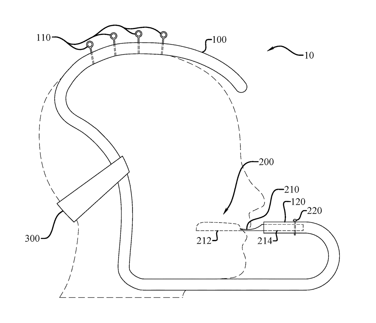
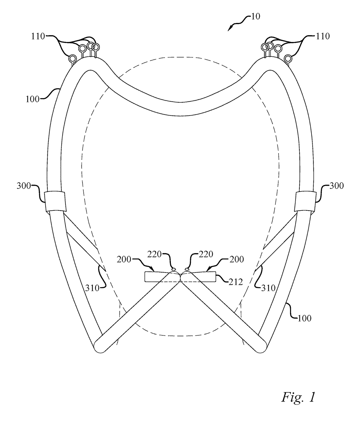
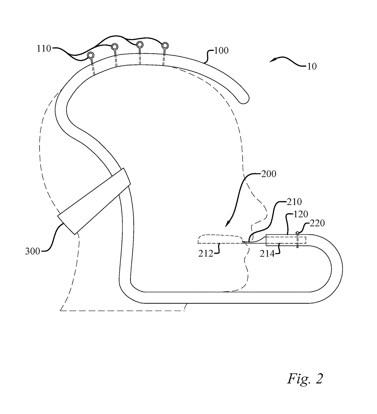
[0021]As seen in FIGS. 1-5, certain embodiments of a cervical traction device may be seen. In one such embodiment, seen well in FIGS. 1-3, a cervical traction device (10) may include a frame (100) and two non-traumatic and releasable skull attachments (200, 300). A first skull attachment (200) may be attached to the frame (100) where it would be and releasably attachable to a skull at an anterior portion of a head on an inferior aspect of a maxilla of a user. Thus upward force would be exerted on the maxilla, and not the mandible as is common in the prior art. There may be a second skull attachment (300) attached to the frame (100) where it would be releasably attachable to the skull at a posterior portion of the head on an inferior aspect of an occiput of the user. Thus, the total upwards traction force could be distributed between the lower back of the head and the maxilla.

[0022]The skull attachments (200, 300) may be fixed to the frame, or they may be releasably attached, and may...


PUM


Abstract

A cervical traction device is provided. A frame presents an anterior support under the maxilla of a user, while a posterior support is applied to the lower portion of the occiput of the user. Thus, pressure is avoided on the potentially unstable mandible, and the lower and upper teeth are not compressed against one another. A series of suspension points on the frame allows the angle at which traction may be applied to the cervical vertebrae to be varied.

Description

STATEMENT REGARDING FEDERALLY SPONSORED RESEARCH OR DEVELOPMENT[0001]Not applicable.TECHNICAL FIELD[0002]The present disclosure relates generally to a device for applying cervical traction to a human user, and to a method of using the same.BACKGROUND OF THE INVENTION[0003]Traction is a therapeutic method to relieve pain by stretching and realigning the spine. Placing a stretch on the spine separates the vertebrae and helps to relieve direct nerve pressure and stress on the vertebral discs. Cervical traction is a common nonsurgical treatment for a herniated disc, and other conditions of the spine and musculature in the neck that relieves pain by opening up the cervical foramen to reduce pressure on compressed nerve roots exiting the spinal canal. Traction can either be applied manually or by spinal traction devices.[0004]The history of traction as a medical instrumentality is lengthy and well-known. The Russian neurologist Osip Mochutkovsky described suspension as a method for the tr...

Claims


Application Information

Patent Timeline
Patent Type & Authority Applications(United States)
IPC IPC(8): A61H1/02A61F5/042
CPCA61H1/0218A61H2201/1664A61H2201/1607A61F5/042A61H1/0296A61H2201/0161A61H2201/0192A61H2201/1604
Inventor SAVAGE, ELTON DEVIN
Owner SAVAGE ELTON DEVIN
Why Eureka
Try Eureka