Augmented reality systems and methods with variable focus lens elements

Active Publication Date: 2017-10-12
MAGIC LEAP
View PDF2 Cites 105 Cited by
  • Summary
  • Abstract
  • Description
  • Claims
  • Application Information

AI Technical Summary

Benefits of technology

[0045]The method of any of Examples 19-22, wherein the one or more waveguides each compri

Problems solved by technology

Because the human visual perception system is complex, it is challenging to produce AR technology that facilitates a comfo

Method used


Image

  • Augmented reality systems and methods with variable focus lens elements
  • Augmented reality systems and methods with variable focus lens elements
  • Augmented reality systems and methods with variable focus lens elements

Examples


Embodiment Construction

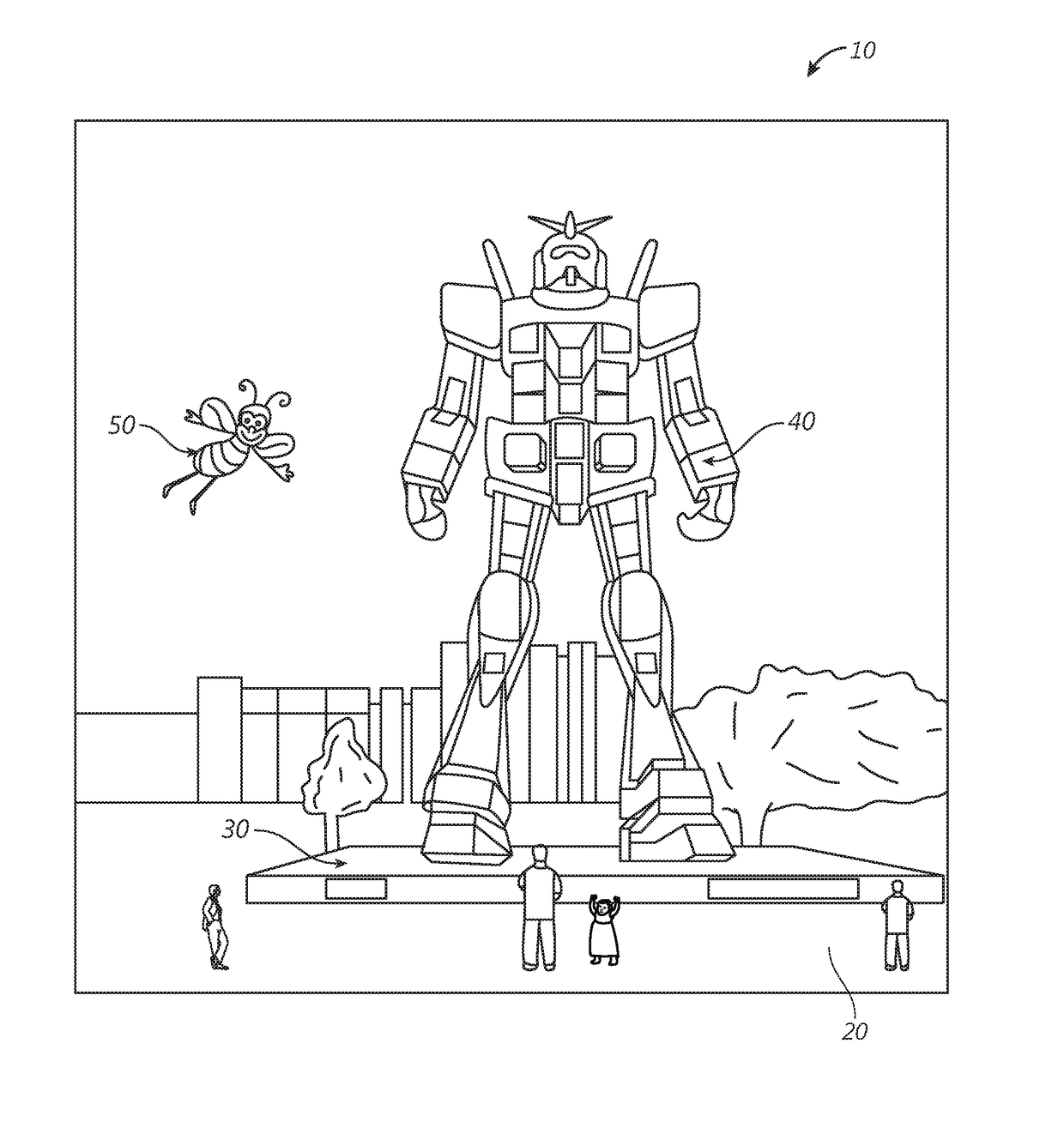
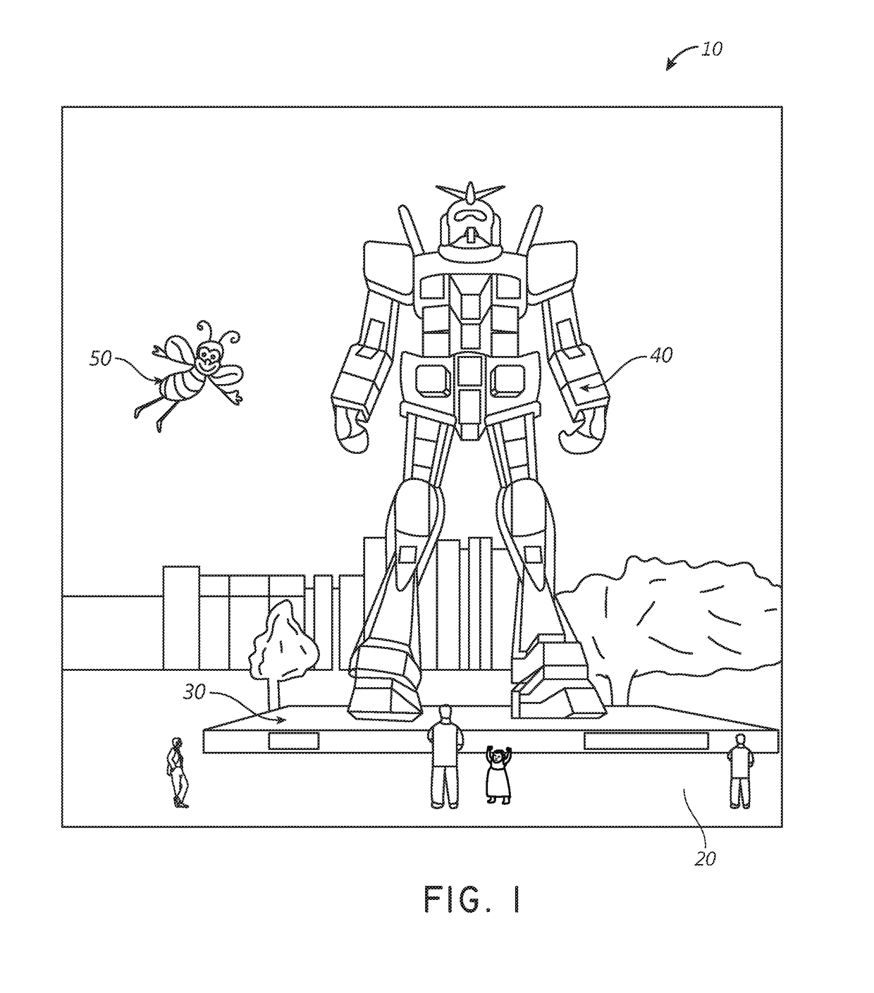
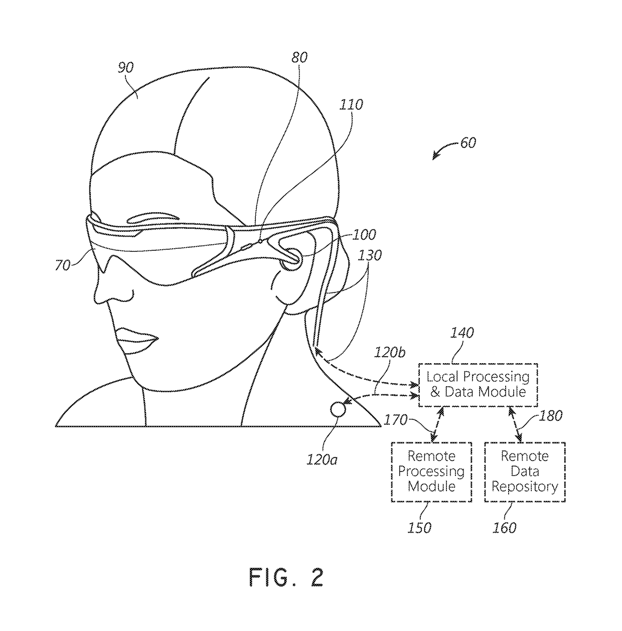
[0061]As disclosed herein, augmented reality (AR) systems may display virtual content to a viewer while still allowing the viewer to see the world around them. Preferably, this content is displayed on a head-mountable display, e.g., as part of eyewear, that projects image information to the viewer's eyes, while also transmitting light from the surrounding environment to those eyes, to allow a view of that surrounding environment.

[0062]Many viewers, however, have eyes with refractive errors that prevent light from correctly focusing on their eyes' retinas. Examples of refractive errors include myopia, hyperopia, presbyopia, and astigmatism. These viewers may require lens elements with a particular prescription optical power to clearly view the image information projected by the display. In some embodiments, such lens elements may be positioned between a waveguide for projecting the image information and the viewer's eyes. Undesirably, these lens elements and possibly other optically ...


PUM


Abstract

An augmented reality display system includes a pair of variable focus lens elements that sandwich a waveguide stack. One of the lens elements is positioned between the waveguide stack and a user's eye to correct for refractive errors in the focusing of light projected from the waveguide stack to that eye. The lens elements may also be configured to provide appropriate optical power to place displayed virtual content on a desired depth plane. The other lens element is between the ambient environment and the waveguide stack, and is configured to provide optical power to compensate for aberrations in the transmission of ambient light through the waveguide stack and the lens element closest to the eye. In addition, an eye-tracking system monitors the vergence of the user's eyes and automatically and continuously adjusts the optical powers of the pair of lens elements based on the determined vergence of those eyes.

Description

PRIORITY CLAIM[0001]This application claims the priority benefit of U.S. Provisional Patent Application No. 62 / 320,375 filed on Apr. 8, 2016, which is incorporated by reference herein in its entiretyINCORPORATION BY REFERENCE[0002]This application also incorporates by reference the entirety of each of the following patent applications: U.S. application Ser. No. 14 / 555,585 filed on Nov. 27, 2014; U.S. application Ser. No. 14 / 690,401 filed on Apr. 18, 2015; U.S. application Ser. No. 14 / 212,961 filed on Mar. 14, 2014; U.S. application Ser. No. 14 / 331,218 filed on Jul. 14, 2014; and U.S. application Ser. No. 15 / 072,290 filed on Mar. 16, 2016.BACKGROUNDField[0003]The present disclosure relates to optical devices, including augmented reality imaging and visualization systems.Description of the Related Art[0004]Modern computing and display technologies have facilitated the development of systems for so called “virtual reality” or “augmented reality” experiences, in which digitally reproduc...

Claims


Application Information

Patent Timeline
IPC IPC(8): G02B27/01G02C11/00G06T19/00G02C7/08G06F3/01G02F1/1335
CPCG02B27/0172G06F3/013G02F1/133502G06T19/006G02C7/083G02B2027/0138G02B2027/011G02B2027/014G02B2027/0178G02F2202/09G02C11/10G02B27/0093G06F1/163G06F3/0304G06F3/011G02F1/294
Inventor MILLER, SAMUEL A.GRECO, PAUL M.SCHOWENGERDT, BRIAN T.
Owner MAGIC LEAP
Why Eureka
Try Eureka