
Variable Track Wheel and Associated Systems and Methods

a track wheel and variable technology, applied in the field of variable track wheels, can solve the problems of driver comfort or even safety problems, and the inability to assemble discs and rims in such a manner, and achieve the effect of improving the stroke and performance of the vehicle on which the wheel is mounted

Active Publication Date: 2017-10-19
TITAN INT
View PDF2 Cites 1 Cited by
  • Summary
  • Abstract
  • Description
  • Claims
  • Application Information

AI Technical Summary

Benefits of technology

The solution ensures precise axial alignment and balanced wheel assembly, reducing vibrations and simplifying spare part replacements, while maintaining effective centering across various configurations, including those with spacers.

Problems solved by technology

One drawback of variable track wheels of known type is that as they are wheels of relatively large dimensions, it is rather difficult to assemble the disc and the rim in such a manner that the respective rotation axes are effectively coaxial.
This axial misalignment between rim and disc has a negative effect on the stroke and performance features of the vehicle on which the wheel is mounted.
In particular, the misalignment causes vibrations that are transmitted to the vehicle, with the risk of causing the driver problems of comfort or even problems of safety due to instability of the vehicle.
The centering systems of known type are not designed for repeating centering during mounting of the disc and of the rim after first mounting.
In fact, during removal of the centering pins or during subsequent inserting of the pins into the corresponding holes, the walls of the holes into which the centering pins have to be inserted for centering can become damaged, this causing possible play that reduces the precision of the subsequent mounting.
Still another drawback of known systems is that in the event of replacement of only the rim or only the disc with a new rim or a new disc, the new rim or the new disc has to be provided with holes or pins having dimensions that are compatible with those found on the piece with which they have to be coupled.
Alternatively, to mount, for example, a new disc on an old rim, it is necessary to work on the old rim or on the new disc, for example, to match the dimensions of the holes with those of the pins, this increasing significantly the time and cost of replacement.
Lastly, the centering systems of known type are not effective on all the types of variable track wheel, in particular on wheels comprising spacers between the disc and connecting member.

Method used


Image

  • Variable Track Wheel and Associated Systems and Methods
  • Variable Track Wheel and Associated Systems and Methods
  • Variable Track Wheel and Associated Systems and Methods

Examples


Embodiment Construction

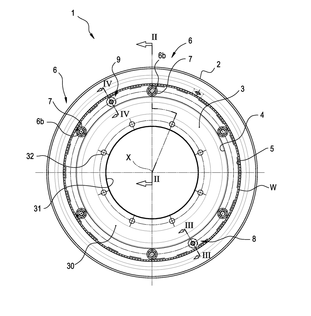
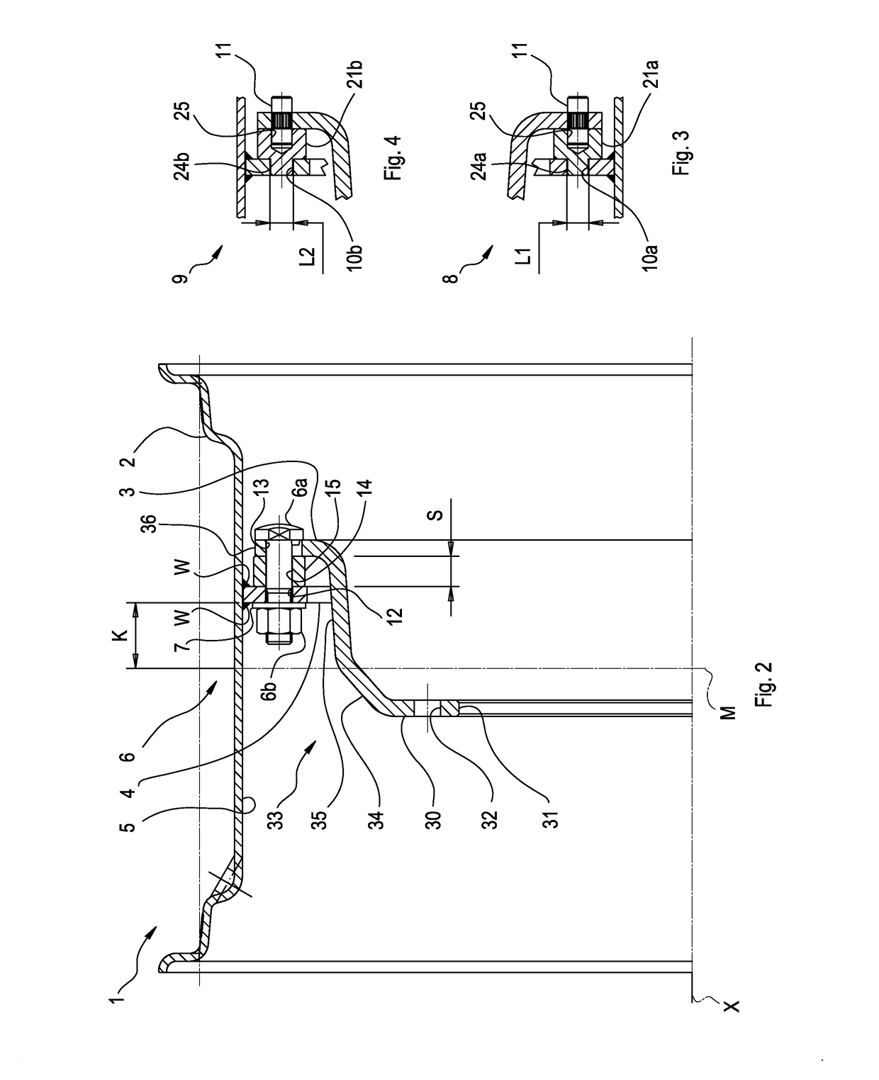
[0031]FIGS. 1 and 2 show a variable track wheel 1, comprising a rim 2 that is suitable for receiving a tire, which is not shown, and a disc 3 through which the wheel 1 is mountable on a hub, which is also shown.

[0032]The rim 2 comprises a connecting member 4, that projects from an internal circumferential surface 5 of the rim 2 to a rotation axis X of the wheel 1.

[0033]The connecting member 4 comprises a circumferentially continuous singular annular element, which is fixed to the internal circumferential surface 5 for example by welding, in particular angular welding, indicated by W in FIGS. 1 and 2.

[0034]In one alternative embodiment that is not shown, instead of a circumferentially continuous singular annular element, the connecting member 4 can comprise a plurality of circumferentially equidistant lobes.

[0035]The connecting member 4 is substantially flat, i.e. extends parallel to a central diametral plane of the rim 2—and thus of the wheel 1, of line M in FIG. 2, at a preset dist...


PUM


Abstract

A variable track wheel comprises a rim suitable for receiving a tire, and a disc through which said wheel is mountable on a hub, said disc being removably secured by fastenings to a connecting member provided in said rim, said connecting member projecting towards a rotation axis of said wheel, said wheel further comprising a plurality of spacers interposed between an annular perimeter zone of said disc and said connecting member of said rim, said disc and said rim being mountable in a plurality of reciprocal axial positions and in a plurality of reciprocal orientations to obtain a variation in the track of said wheel, said wheel further comprising at least one centering device for mutual positioning of said disc and of said rim said centering device comprising a hole and a pin said hole or said pin being provided in said connecting member or in said disc said centering device further comprising a coupling element so conformed as to cooperate with said hole and with said pin for reciprocally coupling said pin and said hole.

Description

CROSS-REFERENCE TO RELATED APPLICATION(S)[0001]This application is a continuation of U.S. application Ser. No. 14 / 367,381, entitled “VARIABLE TRACK WHEEL,” issuing on Jul. 11, 2017 as U.S. Pat. No. 9,701,158, which claimed priority to International Patent Cooperation Treaty Application Serial No. PCT / IB2012 / 057315, filed on Dec. 10, 2012, which claims priority to European Patent Application No. 11194646.3 filed on Dec. 20, 2011, which is incorporated herein in its entirety by this reference.BACKGROUND OF THE INVENTION[0002]The invention relates to a variable track wheel of the type comprising a rim and a disc mounted together in a removable manner.[0003]Variable track wheels comprising a rim are known, on which the tire is mounted, having a cylindrical base on the internal circumferential surface of which there is provided a connecting member that projects radially towards the rotation axis of the wheel. A disc is removably secured to the connecting member, the wheel being fitted to...

Claims


Application Information

Patent Timeline
Patent Type & Authority Applications(United States)
IPC IPC(8): B60B23/12B60B3/00B60B23/10B60B3/04B60B23/00
CPCB60B23/00B60B23/12B60B2310/305B60B2360/10B60B2900/116B60B2900/351B60B3/04B60B3/00B60B23/10
Inventor PELLICANO, PASQUALE PATRIZIODONATI, GRAZIANO
Owner TITAN INT
Learn More