Mobile Auxiliary Transfer Lift Caddy

a technology of auxiliary lifts and caddy wheels, which is applied in the field of hoists and lifts, can solve the problems of not being able to be repaired or maintained by another vehicle, the hoist or hoist can be tied up and idled, and the partially-repaired vehicle cannot be lowered from the lift and moved on its own wheels

Active Publication Date: 2017-10-19
MOTUS MECHATRONICS INC
View PDF13 Cites 9 Cited by
  • Summary
  • Abstract
  • Description
  • Claims
  • Application Information

AI Technical Summary

Benefits of technology

[0009]A further object is to provide an auxiliary lift caddy that can maneuver beneath the chassis or frame of a vehicle on the primary lift and between the primary lift posts, and on which lift arms can be precisely maneuvered to engage the vehicle lift pads and remove the lift pads and vehicle from the stationary primary lift and lock them in place on the lift arms of the mobile machine or caddy.
[0012]Yet another object is that once the vehicle and the lift pads are secured onto the caddy or mobile lift machine, the caddy can transfer the vehicle, under the caddy's own power (under wired or wireless control) away from the stationary primary lift to a different location.

Problems solved by technology

When that happens the lift or hoist can be tied up and idled, and not be available for repairs or maintenance to another vehicle.
However, the partly-repaired vehicle cannot simply be lowered from the lift and moved on its own wheels, especially if it is missing some portion of its suspension.
Currently there are motor-driven wheeled dollies that can support a single wheel of a vehicle while the vehicle is on the lift, but cannot remove the vehicle from the lift or transport the partly-repaired vehicle.
Vehicle-lifting jacks also exist, capable of supporting points on the frame of a vehicle and lifting it so it can be transported, but these do not lift a vehicle from a primary lift or hoist.
No arrangements are currently available that are suited for lifting a vehicle off a fixed, primary lift or hoist, and transporting the vehicle out of a service bay.

Method used


Image

  • Mobile Auxiliary Transfer Lift Caddy
  • Mobile Auxiliary Transfer Lift Caddy
  • Mobile Auxiliary Transfer Lift Caddy

Examples


Embodiment Construction

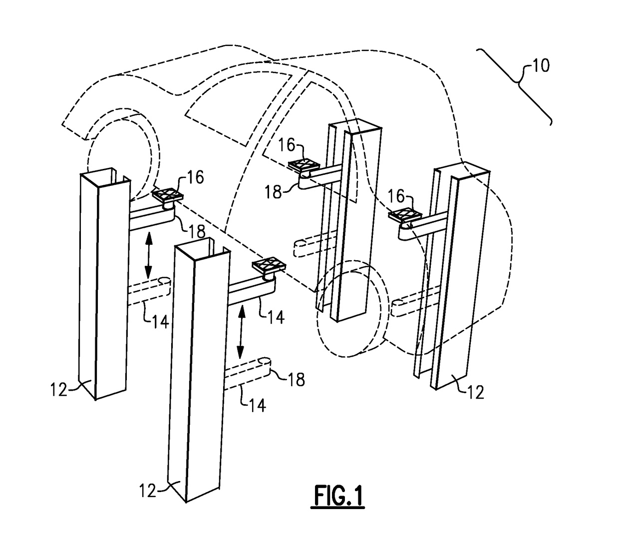
[0052]With reference to the Drawing Figures, and initially to FIG. 1, an automotive repair shop typically employs one or more primary lifts 10, positioned within a respective service bay for the purpose of lifting a vehicle above the floor of the repair bay to facilitate repair or maintenance of the vehicle. As shown, a typical primary or permanent lift 10 has four lift posts 12 that define the workspace around the vehicle, with each lift post 12 having a lift arm 14 that can be extended to position itself under the vehicle. There are lift pads 16 at the distal or outer ends of the lift arms, and these are to be positioned at predetermined lift points on the body or chassis of the vehicle so it can be lifted. In the embodiments of this invention, the lift pads 16 are replaceable and interchangeable, and can be removed from associated sockets or receptacles 18, as discussed later. While not shown here, there are hydraulic cylinders or equivalent actuator mechanisms in each of the lif...


PUM


Abstract

A mobile lift caddy is configured to remove a vehicle from a primary lift while the vehicle is elevated above the workplace floor and then transport the vehicle to another location. The mobile lift caddy is dimensioned to fit between vertical lift posts of the primary lift. A mobility drive arrangement moves the caddy under operator control to and from the workplace location. Caddy lift arms are configured to accept a portion of removable lift pad assemblies at the lift arms of the primary lift, to lift out the lift pad assembly with the vehicle supported on the lift pads.

Description

BACKGROUND OF THE INVENTION[0001]This invention relates to hoists and lifts for raising a motor vehicle above the floor of a workplace, and is more particularly concerned with mobile lift and transport devices for a transferring a vehicle from a primary lift to another location. The invention is more particularly concerned with an arrangement in which the primary lift employs modular removable vehicle lift pads that are positioned in the lift arms of the primary lift and which a mobile lift and transport caddy can accept to lift the vehicle lift pads and the vehicle off the primary lift to free the primary lift for other work.[0002]Automotive repair shops and automotive body shops employ lifts or hoists to raise the vehicle above the workplace floor for purposes of allowing the workers access to the lower portions of a vehicle or to relieve weight from the vehicle suspension to permit repairs to wheels, brakes, etc. It frequently occurs that an automotive repair is only partly compl...

Claims


Application Information

Patent Timeline
Patent Type & Authority Applications(United States)
IPC IPC(8): B60P3/07B66F3/46B65G67/02
CPCB60P3/07B66F3/46B65G67/02B60P3/06B66F7/10B66F7/20B66F7/28B66F9/065B66F9/07577B66F7/00B66F7/0625
Inventor THOMAS, MARC S.
Owner MOTUS MECHATRONICS INC
Why Eureka
Try Eureka