Supercharge Your Innovation With Domain-Expert AI Agents!

Thrust bearing

Active Publication Date: 2017-10-19
GENERAL ELECTRIC CO
View PDF1 Cites 8 Cited by
  • Summary
  • Abstract
  • Description
  • Claims
  • Application Information

AI Technical Summary

Benefits of technology

The patent is about a bearing that can support vibrations in a gas turbine engine. The bearing has a pad with a thrust face that supports these vibrations. There is also a housing that delivers pressurized gas to the pad and a cavity that reduces the vibrations. The housing has two control volumes and two semi-rigid walls that help with the dampening of the vibrations. This design helps improve the performance and stability of the gas turbine engine.

Problems solved by technology

However, the inventors have observed that some gas bearings require a substantial number of assembled components to provide the necessary functionality to meet dynamic loading requirements.
Such a high number of components introduce high complexity, cost, and weight to the gas bearing, thereby limiting potential applications, especially in aerospace gas turbine engines where weight reduction is paramount.
Moreover, the high number of components increases a size of the gas bearing without providing additional functionality, thereby preventing the gas bearing from being utilized within space limited locations throughout the gas turbine engines, such as aircraft engines.

Method used


Image

  • Thrust bearing
  • Thrust bearing
  • Thrust bearing

Examples


Embodiment Construction

[0022]Reference will now be made in detail to present embodiments of the invention, one or more examples of which are illustrated in the accompanying drawings. The detailed description uses numerical and letter designations to refer to features in the drawings. Like or similar designations in the drawings and description have been used to refer to like or similar parts of the invention. As used herein, the terms “first”, “second”, and “third” may be used interchangeably to distinguish one component from another and are not intended to signify location or importance of the individual components. The terms “upstream” and “downstream” refer to the relative direction with respect to fluid flow in a fluid pathway. For example, “upstream” refers to the direction from which the fluid flows, and “downstream” refers to the direction to which the fluid flows.

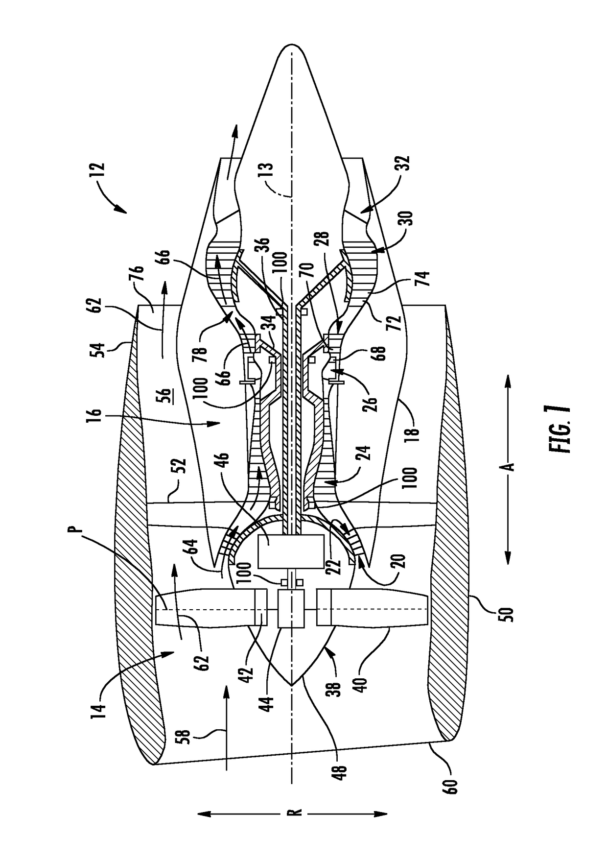
[0023]Referring now to the drawings, wherein identical numerals indicate the same elements throughout the figures, FIG. 1 is a schematic...


PUM


Abstract

A bearing including a bearing pad and a housing is provided. The bearing pad has a thrust face for supporting a vibration along an axial direction of the bearing. Additionally, the housing is formed integrally using an additive manufacturing process and is attached to or formed integrally with the bearing pad. The housing defines a working gas delivery system for providing a flow of pressurized working gas to the thrust face of the bearing pad and a fluid damper cavity. The fluid damper cavity provides a dampening of the axial vibration supported by the thrust face of the bearing pad along the axial direction.

Description

FIELD OF THE INVENTION[0001]The present subject matter relates generally to an air bearing, or more particularly to a thrust air bearing that may be used in a gas turbine engine.BACKGROUND OF THE INVENTION[0002]A gas turbine engine generally includes a fan and a core arranged in flow communication with one another. Additionally, the core of the gas turbine engine generally includes, in serial flow order, a compressor section, a combustion section, a turbine section, and an exhaust section. In operation, air is provided from the fan to an inlet of the compressor section where one or more axial compressors progressively compress the air until it reaches the combustion section. Fuel is mixed with the compressed air and burned within the combustion section to provide combustion gases. The combustion gases are routed from the combustion section to the turbine section. The flow of combustion gasses through the turbine section drives the turbine section and is then routed through the exhau...

Claims


Application Information

Patent Timeline
IPC IPC(8): F01D25/16F16C17/04F16C32/06
CPCF01D25/164F16C32/0614F16C17/047F05D2220/32F05D2240/53F05D2260/96F05D2240/52F16C32/0625F16C32/0666F16C32/067F16C35/00F16C32/0677F16C27/02F16C32/0622F16C2360/23
Inventor ERTAS, BUGRA HANMOOK, JOSHUA TYLERBELLARDI, JASON JOSEPH
Owner GENERAL ELECTRIC CO
Features
  • R&D
  • Intellectual Property
  • Life Sciences
  • Materials
  • Tech Scout
  • Unparalleled Data Quality
  • Higher Quality Content
  • 60% Fewer Hallucinations
Learn More