Spinning rotor shaft, bearing arrangement for the active magnetic support of such a spinning rotor shaft and spinning rotor drive device

a technology of bearing arrangement and spinning rotor shaft, which is applied in the direction of magnetic bearings, open-end spinning machines, mechanical instruments, etc., can solve the problems of affecting the positioning precision and the operation of the spinning rotor

Active Publication Date: 2017-10-19
SAURER SPINNING SOLUTIONS GMBH & CO KG
View PDF6 Cites 8 Cited by
  • Summary
  • Abstract
  • Description
  • Claims
  • Application Information

AI Technical Summary

Benefits of technology

[0026]Furthermore, preferably the shaft section designed for conducting the electromagnetic flux ensuring the radials bearing is a separate component from the spinning rotor shaft which can be mounted on the spinning rotor shaft. The shaft section can thereby be pushed in a preferred manner onto the spinning rotor shaft up to a defined position and / or can be positioned in a recess assigned to the shaft section in the casing surface of the spinning rotor shaft. The spinning rotor shaft can thereby be designed to be simple and inexpensive, where the magnetic flux conducting shaft sections can be configured and arranged according to the requirements of the bearing arrangement. Thus a spinning rotor shaft can be provided for various different designs of bearing arrangements, wherein the respective shaft section adjusted to the bearing arrangement can be placed in a defined position along the shaft longitudinal axis or axis of rotation, in particular to be replaceable. The fixed positioning of the shaft section directed along the shaft longitudinal axis or axis of rotation of the spinning rotor shaft can be performed in a suitable manner for example by means of engaging and / or bearing elements on the spinning rotor shaft and / or the shaft section.
[0027]In particular the spinning rotor shaft is adjusted to the aforementioned bearing arrangement by the active magnetic axial bearing comprising a first and second electromagnet or designed for the latter. The spinning rotor shaft also comprises in the effective area of the first and second electromagnet a casing surface section, which is designed to be step-like in cross-section, or has a contour designed to be step-like along the axis of rotation of the spinning rotor shaft for producing reluctance forces directed in opposite directions. The step-like configuration in cross-section creates in the effective area of the respective electromagnet a different spacing of the respective casing surface section from the assigned electromagnet, in order to conduct the produced electromagnetic flux as required into the spinning rotor shaft so that the controllable, axial reluctance force component suitable for positioning or displacing can be produced on the spinning rotor shaft.
[0028]According to an alternatively preferred embodiment the spinning rotor shaft is adjusted to the aforementioned bearing by the active magnetic axial bearing comprising the permanent magnetic pole or the magnetic flux conducting material and the electromagnet. The spinning rotor shaft made from a magnetic flux conducting material for this purpose on its end face shaft end, which is provided for the opposite arrangement to the active magnetic axial bearing, provided that the active magnetic axial bearing comprises the permanent magnetic pole. Alternatively, the spinning rotor shaft on the end face shaft end can have a permanent magnetic pole such as a north or south pole, which is different from the latter as long as the active magnetic axial bearing comprises a permanent magnetic pole. Thus between the end face shaft end and the active magnetic axial bearing during operation a magnetic force of attraction can be ensured.
[0029]According to a further aspect of the present invention a spinning rotor drive device for an open-end spinning device comprising a drive housing with a bearing arrangement according to any one of the preceding embodiments is proposed in connection with a suitable designed spinning rotor shaft according to any one of the preceding embodiments. The spinning rotor shaft is supported in particular replaceably in the bearing arrangement. Thus for the open-end spinning device a drive unit designed as a unit with coordinated components can be provided for a spinning rotor, for which also preferably a rotor cup needs to be coupled to the spinning rotor shaft or the spinning rotor shaft is already coupled to a rotor cup for forming a spinning rotor or is designed in one piece. The spinning rotor shaft comprises for the coupling a conventional torque-transmitting coupling point.
[0030]Further features and advantages of the invention are explained in the following description of preferred example embodiments of the invention, with reference to the figures and drawings and from the claims. The individual features can be implemented alone or in any combination in a preferred embodiment of the invention.

Problems solved by technology

However, said magnet bearings due to their configuration and the corresponding design of the spinning rotor shaft are subject to a speed limit, which prevents the operation of the spinning rotor coupled to the spinning rotor shaft at speeds significantly greater than 200,000 min−1.
Furthermore, the respectively used passive magnetic radial or axial bearing necessitates less rigidity in the corresponding bearing direction, which means that the precision of the positioning can be influenced negatively.

Method used


Image

  • Spinning rotor shaft, bearing arrangement for the active magnetic support of such a spinning rotor shaft and spinning rotor drive device
  • Spinning rotor shaft, bearing arrangement for the active magnetic support of such a spinning rotor shaft and spinning rotor drive device
  • Spinning rotor shaft, bearing arrangement for the active magnetic support of such a spinning rotor shaft and spinning rotor drive device

Examples


Embodiment Construction

[0038]In the following description of example embodiments according to the present invention the same or similar reference numerals are used for the similarly acting elements shown in the different figures, wherein said elements are not described more than once.

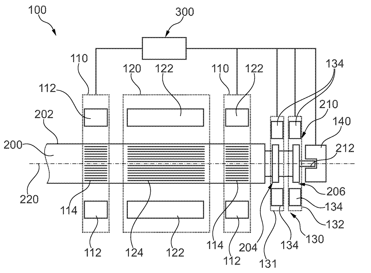
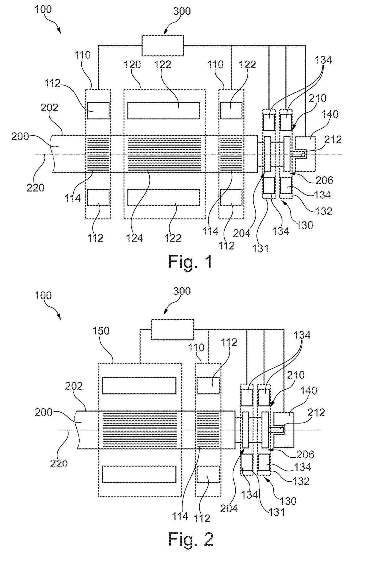
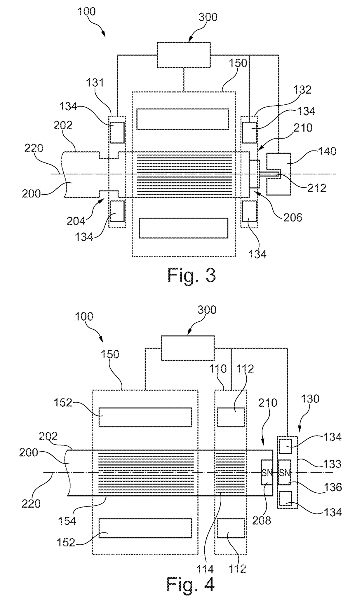
[0039]FIGS. 1 to 6 show in a schematic representation a bearing arrangement 100 with a spinning rotor shaft 200 according to a first to sixth example embodiment.

[0040]The bearing arrangement 100 according to the first example embodiment shown in FIG. 1 comprises two active magnetic radial bearings 110 which in an arrangement direction frame both sides of a motor 120 for driving the circular cylindrical spinning rotor shaft 200 designed as a smooth shaft. The motor 120 is a conventional direct current motor commutated accordingly for the rotary drive of a spinning rotor shaft with a winding package 122 in the stator and a permanent magnet 124 coupled to the spinning rotor shaft 200 in the rotor.

[0041]The respective active magn...


PUM

PropertyMeasurementUnit
magnetic forceaaaaaaaaaa
magnetic fluxaaaaaaaaaa
electromagnetic fluxaaaaaaaaaa

Abstract

A bearing arrangement (100) for a spinning rotor shaft (200) of an open-end spinning device, a spinning rotor shaft (200) for such a bearing arrangement (100) and a spinning rotor drive device comprising such a bearing arrangement (100) and such a spinning rotor shaft (200). The bearing arrangement (100) comprises at least one active magnetic radial bearing (110) for the spinning rotor shaft (200) which can be influenced by means of an electronic control system (300). The bearing arrangement is characterized in that the bearing arrangement (100) comprises an active magnetic axial bearing (130) for the spinning rotor shaft (200) which can be influenced by means of the or another electronic control system (300).

Description

CROSS-REFERENCE TO RELATED APPLICATIONS[0001]This application claims priority from German National Patent Application No. DE 10 2016 004 714.32, filed Apr. 19, 2016, entitled “Spinnrotorschaft, Lageranordnung zum aktiven magnetischen Lagern eines solchen Spinnrotorschafts and Spinnrotorantriebseinrichtung”, the entire contents of which are incorporated herein by reference.FIELD OF THE INVENTION[0002]The invention relates to a bearing arrangement for the active magnetic support of a spinning rotor shaft of an open-end spinning device, a spinning rotor shaft for active magnetic support in such a bearing arrangement as well as a spinning rotor drive device comprising such a bearing arrangement with a corresponding spinning rotor shaft.BACKGROUND OF THE INVENTION[0003]In German Patent Publication DE 10 2014 104 531 A1 a magnet bearing for a spinning rotor is disclosed, which is based on a combination of an active magnetic radial bearing with a passive magnetic axial bearing. In this cas...

Claims


Application Information

Patent Timeline
Patent Type & Authority Applications(United States)
IPC IPC(8): F16C32/04H02K7/09H02K11/30
CPCF16C32/0485F16C32/0465H02K11/30H02K7/09F16C32/0468D01H4/14F16C32/047F16C32/048F16C2340/18D01H4/12F16C32/0442F16C32/0476F16C32/0493
Inventor BRAKENSIEK, DIRKBURCHERT, MATTHIAS
Owner SAURER SPINNING SOLUTIONS GMBH & CO KG
Why Eureka
Try Eureka