
Adjustable Archery Arrow Insert

a technology of inserts and arrow tips, applied in the field of archery, can solve the problems of reusing traditional arrow tips and their methods of attachment, which are typically permanently attached, and can not be reused with an alternative arrow shaft, so as to reduce the amount of force absorbed and adjust the degree of weight

Inactive Publication Date: 2017-10-19
ALDILA GOLF CORP
View PDF8 Cites 5 Cited by
  • Summary
  • Abstract
  • Description
  • Claims
  • Application Information

AI Technical Summary

Benefits of technology

The present invention provides an adjustable archery arrow with an insert that removes the arrow tip from the shaft, which helps to minimize contact between the tip and the shaft and reduces the force absorbed by the front edge of the shaft. The weight of the insert can be adjusted to meet different specifications. Additionally, the three pieces of the archery arrow shaft insert can be interchanged with alternative versions to adjust the overall weight of the arrow.

Problems solved by technology

There are several disadvantages to these traditional arrow tips and their method of attachment.
A particular disadvantage of directly mounting the arrow tips to the arrow shafts is that they are typically permanently affixed to the arrow shafts.
Additionally, if the arrow shaft breaks the tip would not be able to be reused with an alternative arrow shaft.
Another disadvantage is that the arrow tip delivers a majority of the impact forces to the front edge of the arrow shaft thereby damaging it.
Particularly in carbon fiber arrow shafts, the forces of the by on the arrow shaft eventually degrades the epoxy resulting in the fraying of the individual carbon fibers.
However, in both cases, the majority of the impact is still absorbed by the front edge of the arrow shaft thereby leading to eventual failure of the front edge arrow of the shaft after periods of use.
Although the disadvantages of the traditional arrow tip and arrow shaft have been addressed by the prior art, the prior art has failed to create a solution to overcome all of the disadvantages.

Method used


Image

  • Adjustable Archery Arrow Insert
  • Adjustable Archery Arrow Insert
  • Adjustable Archery Arrow Insert

Examples


Embodiment Construction

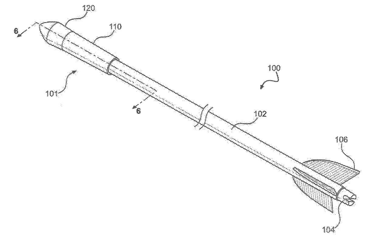
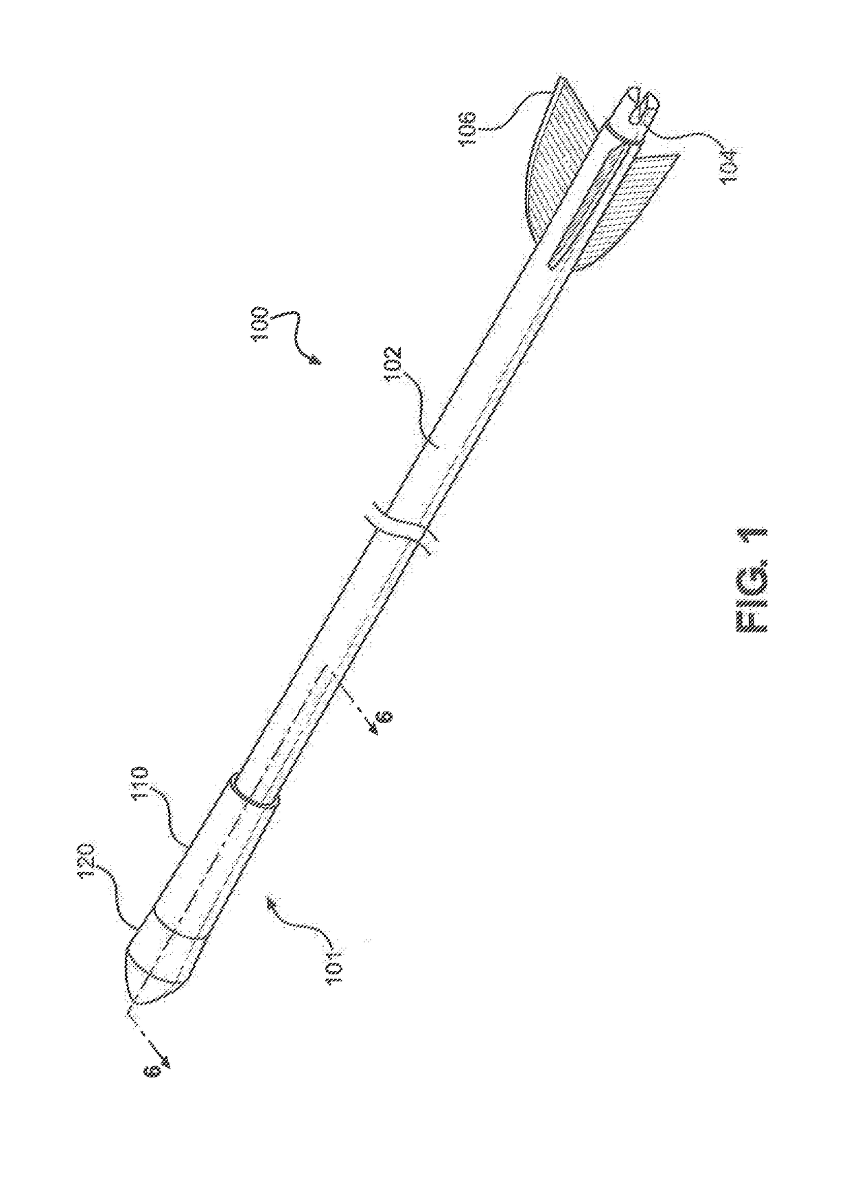
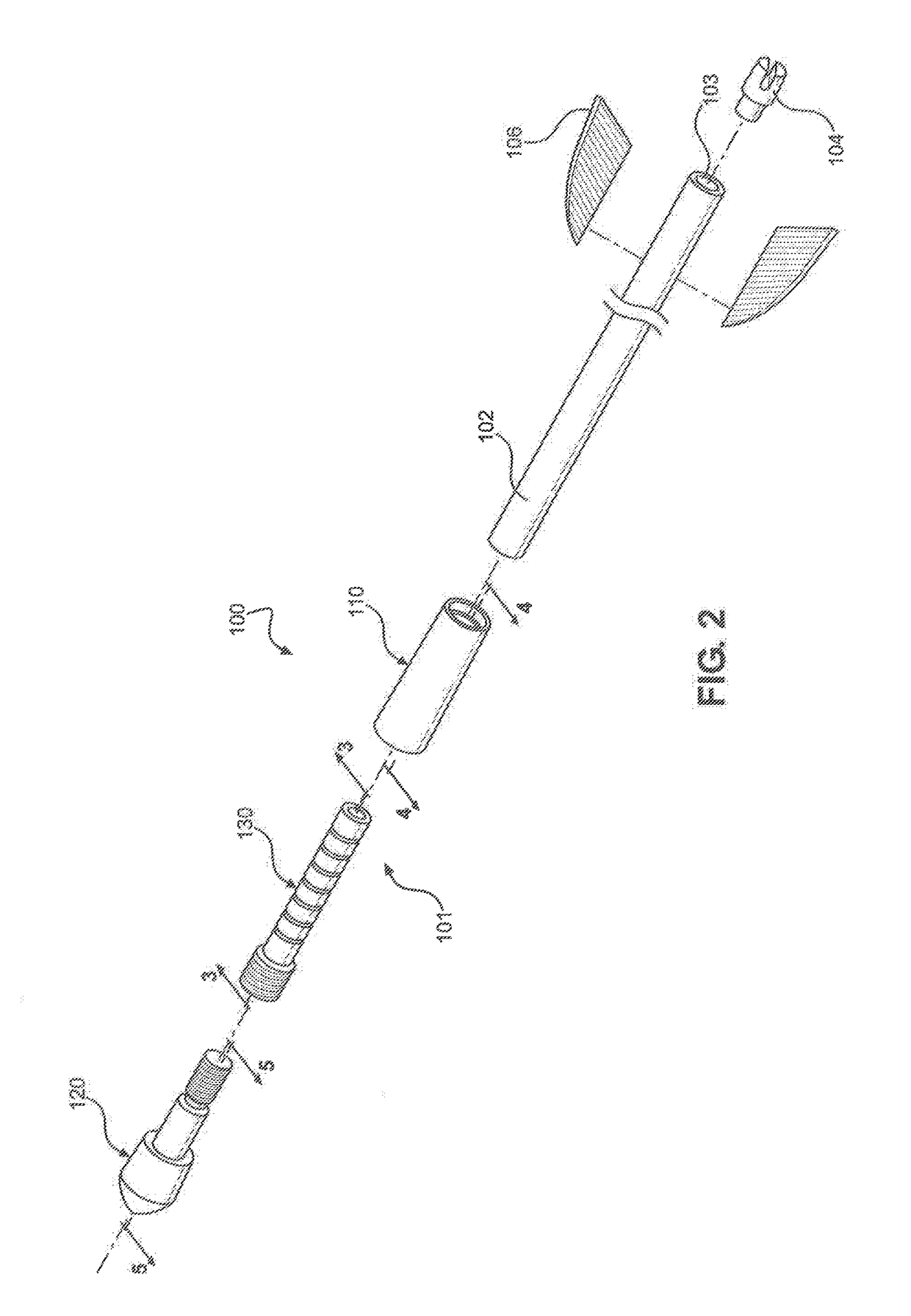
[0028]Referring initially to FIG. 1, a perspective view of an arrow having an Adjustable Archery Arrow Insert 101 attached is shown and generally designated 100. The arrow 100 includes an arrow shaft 102 with a front end and a tail end. At the tail end of arrow shaft 102, a nock 104 is attached. Adjacent the nock 104 and attached to the exterior of the arrow shaft 102 is fletching 106. Attached to the front end of the arrow shaft 102 is the Adjustable Archery Arrow Insert 101 of the present invention, which includes an arrow tip collar 110, an arrow tip 120 and arrow tip insert 130 (shown in FIG. 2). Arrow tip insert 130 is fixedly attached to the arrow shaft 102. An arrow tip collar 110 is threadably attached to the arrow tip insert 130. An arrow tip 120 is threadably attached to the arrow tip insert 130 and contacts the front edge of the arrow tip collar 110.

[0029]Referring now to FIG. 2, an exploded view of the arrow 100 is shown. The arrow shaft 102 is formed with an internal bo...


PUM


Abstract

The Adjustable Archery Arrow Insert is a three-piece arrow tip attached to an arrow shaft and includes an arrow tip insert, an arrow tip collar, and an arrow tip. The arrow tip insert is threadably received by the arrow tip collar and is attached to the arrow shaft, where the arrow tip is inserted within, and the arrow tip collar overlaps, the arrow shaft. The arrow by is inserted through the arrow tip collar and attached directly to the arrow tip insert without protruding into the arrow shaft. Sections of the arrow tip insert may be removed to adjust the overall weight of the arrow. The Adjustable Archery Arrow Insert transfers the impact forces of the arrow tip to the arrow tip insert and arrow tip collar, where the forces are transferred over a larger area thereby minimizing the forces on front edge of the arrow shaft.

Description

RELATED APPLICATION[0001]This application is a continuation-in-part of U.S. patent application Ser. No. 15 / 231,694 entitled “Adjustable Archery Arrow Insert” filed on Aug., 2016 and is currently co-pending, which is a continuation application of U.S. patent application Ser. No. 14 / 799,465 entitled “Adjustable Archery Arrow Insert” filed on Jul. 14, 2015, and now issued as U.S. Pat. No. 9,410,773, which claims the benefit of, and priority to, U.S. Provisional Patent Application No. 62 / 024,413 entitled “Adjustable Archery Arrow Insert” filed on Jul. 14, 2014.FIELD OF INVENTION[0002]The present invention relates generally to archery. The present invention is more particularly, though not exclusively, related to arrow tip inserts utilized to removably attach arrow tips to an arrow shaft.BACKGROUND OF THE INVENTION[0003]An arrow includes an arrow shaft having a tip, a nock, and fletching. Traditionally, arrow tips are mounted directly to the arrow shaft. Arrow tips have a point with a pr...

Claims


Application Information

Patent Timeline
Patent Type & Authority Applications(United States)
IPC IPC(8): F42B6/04F42B6/08
CPCF42B6/08F42B6/04
Inventor GREENWOOD, STEPHEN
Owner ALDILA GOLF CORP
Learn More