Eureka AIR delivers breakthrough ideas for toughest innovation challenges, trusted by R&D personnel around the world.

Rapid process integration through visual integration and simple interface programming

a visual integration and process technology, applied in computing, instruments, electric digital data processing, etc., can solve the problems of complex computer programs, difficult problems, complex computer technology, etc., and achieve the effect of simplifying object interaction, code reuse, and object modularity

Inactive Publication Date: 2013-08-29
HOSICK ERIC
View PDF14 Cites 5 Cited by
  • Summary
  • Abstract
  • Description
  • Claims
  • Application Information

AI Technical Summary

Benefits of technology

The patent text is about a method that simplifies how objects interact with each other. It does this by using properties instead of language syntax and parameters. This makes the code more reusable and easier to modify. The technical effect is better functionality and flexibility in object interaction.

Problems solved by technology

Translating human knowledge into computerized form to enable a computer to perform a useful task is a difficult problem that has existed since the advent of computers.
Whereas, at the beginning of the computer revolution, computer programs were rudimentary in nature, and required extensive skill on the part of end users, computer technology has now evolved to the point that computer programs are much more complex, often making computers much simpler to use.
This makes the modeling and implementation of rapidly changing process very difficult using object-oriented modeling and programming.
However changes to an object's interface can result in adverse effects such as cascading changes throughout a software program.
Since the changes are done at the source code level by people who have knowledge of software engineering, and not by people with the domain knowledge, these changes are often difficult to implement and can lead to increased costs and wasted time.
However, such attempts have led to architectures that are complex, highly specialized, domain specific, bulky and non-standardized.
The source-code of some of the earliest software programs programming languages were unstructured and did not naturally provide constructs to group together functional aspects of a computing system.
However, for units of work that process more complex information, functions do not work as well.
This is because the communication of information with functions and storage of that information becomes more and more difficult as the structural complexity of the information increases: the method signature also becomes complex.
This causes functions to become less effective as we attempt to group together smaller units of work into larger units of work.
If the information being submitted to the function is complex then the method signature of the function must also be complex.
An increase in complexity of a functions signature leads to a lot more overhead when a developer needs to make changes to the interface of functions.
With so many functions, managing groups of functions that did processing on similar information becomes overwhelming.
This also leads to one of the big problems with structured programming.
However, objects still have interfaces (made up of method signatures and properties) and when those interfaces need to change, developers still have the same problems they had in structural programming.
Further, object-oriented programming does not intrinsically contain any methodologies for managing information between objects at the program level nor does it provide developers with any consistent way of creating object interfaces.
This leads to software that contains objects that are less re-usable.
One of the primary reasons for a lack of a consistent and globally agreed upon architecture is due to the complex nature of objects and their interfaces.
Because objects can have dynamic and complex interfaces, it is highly un-likely that two different companies will come up with the same process of communication between objects.
It is even more un-likely that two companies could agree on a consistent architecture by which objects communicate within.
This further leads to objects that are less re-usable.
Writing software is an expensive and time consuming process.
Leveraging off of existing programs in highly desirable but often not attained.
Creating a consistent way of interfacing with objects is difficult at the very least.
The assembly of modules might require more effort and / or time due to the increased inter-module dependency.
Thus a particular module might be harder to reuse and / or test because dependent modules must be included.
A challenging aspect of programming is updating method signatures and interfaces to accommodate changes, for example due to changing processes or business logic.
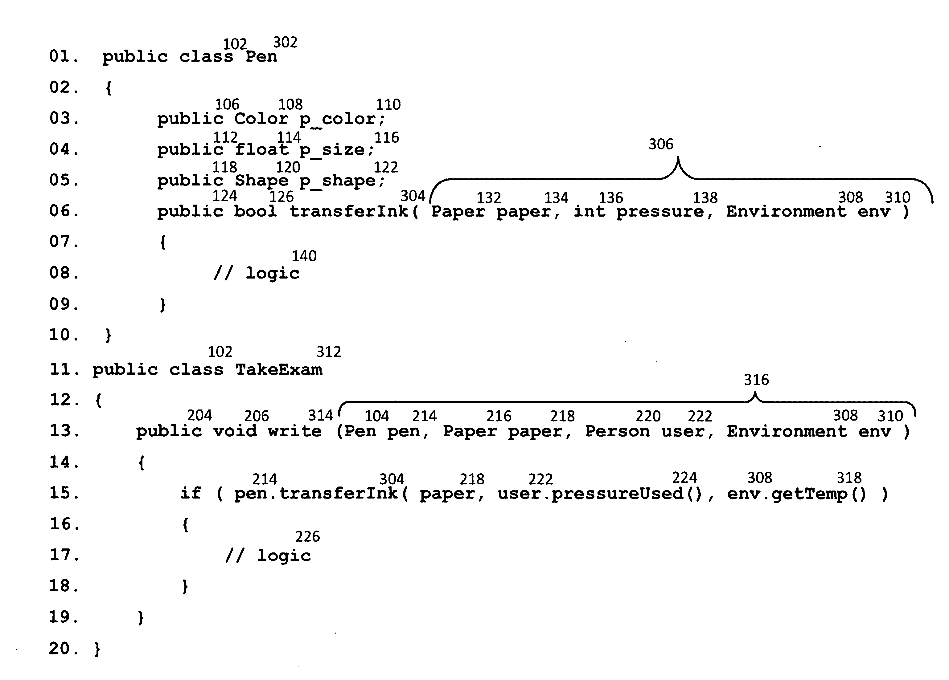
This leads to increased cross cutting concerns and generally hinders the development of fully modular source code. FIG. 3 depicts a conventional process of updating method signatures to accommodate changes.
Due to an effectively infinite combination of object interfaces and interactions, industry wide standardization of object interaction is a difficult and daunting task.

Method used


Image

  • Rapid process integration through visual integration and simple interface programming
  • Rapid process integration through visual integration and simple interface programming
  • Rapid process integration through visual integration and simple interface programming

Examples


example 1

[0087]FIG. 8 depicts an application of the methods discussed herein. A static 802 Main 806 which returns void 804 is declared. Main 806 is a standard way by which a program describes the entry point into a program from an operating system. However, the name doesn't have to be main nor does it need to return a void 804 and so on. One experienced in the arts will simply recognize Line 01 as an entry to a program.

[0088]Ccm 808 is of type RootCCM 502 created through constructor RootCCM( ) 810. Ccm 808 is added to ThreadManager 402 through add 414. After ccm 808 is added to ThreadManager 402 a pen is created and added to CCM starting at Line 06. iPen 812 of type Pen 602 is created by calling constructor Pen( ) 814. iPen 812 has property id 816 which is assigned a string with the value of “pen”818. iPen 812 is then added to composite 506 of the ccm 808. iLocator 820 of type RootCCMLocator 520 is created by calling constructor RootCCMLocator( ) 822. itemToFind 524 or iLocator 820 is assign...

example 2

[0092]Referring to FIG. 9, RootCCM 502 has been further described in RootCCM 902. Composite 506 of type object[ ]504 is an aggregate responsible for storage of data exactly similar as that described in FIG. 5. itemToRun 906 of type object 904 contains the necessary configuration to decide what action to take when withObject 910 is called. Specifically, this logic is described in scope get 912. withObject 910 of type object 908 is providing the common access behavior for RootCCM 902. Starting with Line 11, withObject 916 is called on itemToRun 906 and the resulting object is set in itemToExecute 914. The value of itemToRun 906 could be an instance of any object. Based on existing examples, itemToRun 906 could be an instance of Pen 602, TakeExam 702 or even RootCCM 902. Line 12, withObject 918 of itemToExecute 914 is called and the result returned. Once again, the result object in itemToExecute 914 could be an instance of any object including, but not limited to, example objects Pen 6...

example 3

[0098]Referring to FIG. 11, another approach to access of CCM within properties is provided. The contents of FIG. 11 relate to RootCCMLocator 1102 are logically similar to the contents of FIG. 5 RootCCMLocator 502. In FIG. 05, access to CCM is done through ThreadManager 402. In another aspect of the present invention, access to CCM is provided by an implied parameter. Memory 1014 is an implied parameter passed to actualValue 1110. Value 1118 is also an implied parameter to actualValue 1110.

[0099]When accessing scope get 1012 within a program, implied parameters memory 1014 is passed to property actualValue 1110. Memory 1014 provides access to RootCCM 502. Line 08 of FIG. 11 is logically similar to Line 18FIG. 5. When accessing scope set 1116, implied parameters value 1118 and memory 1014 are passed to property actualValue 1110. Line 12 of FIG. 11 is logically similar to Line 22FIG. 5. In both cases, ThreadManager 402 is no longer required to obtain access to CCM.

CCM Memory

[0100]Refe...


PUM


Abstract

In a first aspect, the invention features a method. A method of simplifying object interaction comprises defining objects whose public interface contains only properties; creating structured data objects; locating references to objects in the structured data object; associating said structured data object with at least one thread; locating said references; initializing said objects; accessing said objects; wherein said objects are persist-able; wherein said properties contain values or locators containing a reference to values.

Description

TECHNICAL FIELD[0001]The invention is generally related to computing devices and computer software. More specifically, the invention is generally related to programming languages and computer management of dynamic logical entities such as objects and the like and communication between these dynamic entities through visual integration as opposed to programmatic integration.BACKGROUND[0002]Translating human knowledge into computerized form to enable a computer to perform a useful task is a difficult problem that has existed since the advent of computers. Humans tend to think in terms of abstract concepts and the meanings behind such concepts. Computers are more literal in nature expecting specific inputs and outputting specific responses to such inputs. To bridge the gap between humans that desire to perform tasks, and the computers that ultimately perform those tasks, skilled software programmers are required to develop computer programs that minimize the level of skill required by e...

Claims


Application Information

Patent Timeline
Patent Type & Authority Applications(United States)
IPC IPC(8): G06F9/44
CPCG06F8/315
Inventor HOSICK, ERIC KEITH
Owner HOSICK ERIC
Why Eureka
Eureka Blog
Learn More