Method for determining measurement conditions of a roughness sensor, method for measuring a roughness of a workpiece surface, computer program product, and measuring device designed to perform the methods

Inactive Publication Date: 2017-10-19
CARL ZEISS IND MESSTECHN GMBH
View PDF0 Cites 5 Cited by
  • Summary
  • Abstract
  • Description
  • Claims
  • Application Information

AI Technical Summary

Benefits of technology

[0006]It is therefore an object of the present invention to provide a method, with the aid of which a simple, compact, and cost-effective roughness sensor suitable for production may be realized. Moreover, the invention solves the problem th

Problems solved by technology

However, a disadvantage of a roughness sensor in accordance with document DE 44 37 033 A1 is that the latter is very sensitive, which often also leads to unnoticed measurement inaccuracies or malfunctions, and therefore, thi

Method used


Image

  • Method for determining measurement conditions of a roughness sensor, method for measuring a roughness of a workpiece surface, computer program product, and measuring device designed to perform the methods
  • Method for determining measurement conditions of a roughness sensor, method for measuring a roughness of a workpiece surface, computer program product, and measuring device designed to perform the methods
  • Method for determining measurement conditions of a roughness sensor, method for measuring a roughness of a workpiece surface, computer program product, and measuring device designed to perform the methods

Examples


Embodiment Construction

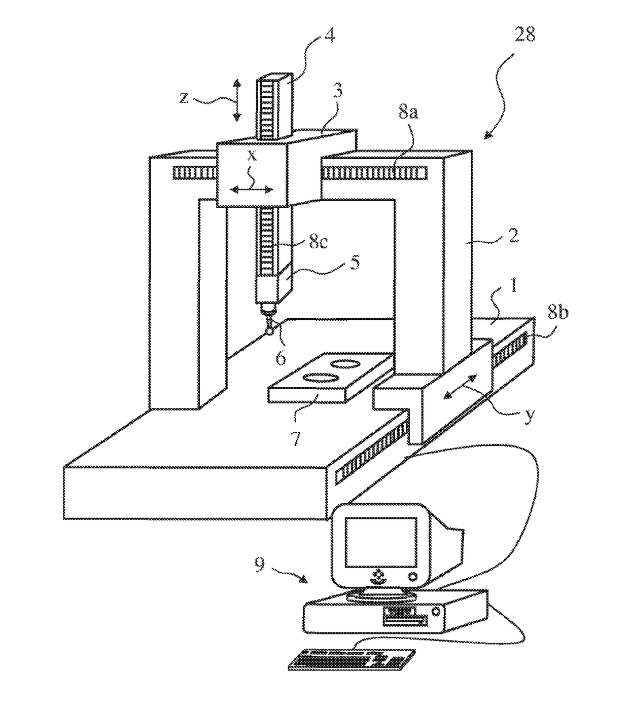
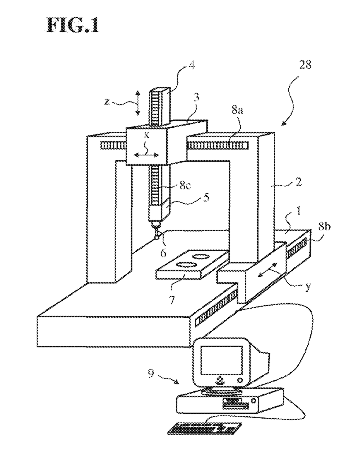
[0026]FIG. 1 shows a coordinate measuring device 28 with a quill 4 with a so-called portal design in a purely exemplary manner. However, it is understood that the present invention may be used in all coordinate measuring devices, in particular, in coordinate measuring devices with a bridge or stand design, and in arm or robot coordinate measuring devices. Hence, the expression coordinate measuring device within the scope of the present application extends to all of the aforementioned coordinate measuring devices and variations thereof.

[0027]The coordinate measuring device 28 shown in FIG. 1 has a stylus 6, which is fastened in a replaceable manner to a measuring head or probe head 5, and which may be deflected in relation to the probe head 5 in three coordinate directions x, y and z. The deflection of the stylus 6 in the three coordinate directions x, y and z is detected by way of three transducers located in the probe head 5. The probe head 5 in turn may be moved in the three coord...


PUM


Abstract

A method for determining measurement conditions of a roughness sensor having at least one measuring needle, a computer program product and a measuring device for carrying out the method are provided. The measuring needle is positioned on a surface in a rest state and rests on the surface without being moved. Measurement signals are recorded in the rest state. A signal line of the roughness sensor is electrically grounded and measurement signals are recorded in the grounded rest state. Further, a method for measuring a roughness of a workpiece surface by the roughness sensor is provided in which the measuring needle is guided along a surface section of the workpiece surface to be measured and moved in a measurement direction (x-direction). The movement of the measuring needle in a plane (yz-plane) perpendicular to the measurement direction is recorded during the movement of the measuring needle along the workpiece surface.

Description

CROSS REFERENCE TO RELATED APPLICATIONS[0001]This application is a continuation application of international patent application PCT / EP2016 / 051298, filed Jan. 22, 2016, designating the United States and claiming priority to German application 10 2015 203 369.4, filed Feb. 25, 2015, and the entire content of both applications is incorporated herein by reference.TECHNICAL FIELD[0002]The present invention relates to a method for determining measurement conditions of a roughness sensor, a method for measuring the roughness of a workpiece surface, a computer program product for controlling the roughness sensor according to the methods, and a measuring device which is configured to carry out the methods.BACKGROUND[0003]By way of example, roughness sensors and measuring devices for measuring the roughness of a workpiece surface are known from U.S. Pat. No. 6,357,286, document DE 102 30 009 A1, U.S. Pat. No. 7,347,084, U.S. Pat. No. 7,827,856, document DE 201 20 127 U1, document DE 20 2013 1...

Claims


Application Information

Patent Timeline
IPC IPC(8): G01B5/28G01B11/30G01B11/00
CPCG01B5/28G01B11/00G01B11/30
Inventor MAYINGER, PHILIPP
Owner CARL ZEISS IND MESSTECHN GMBH
Why Eureka
Try Eureka