Unlock instant, AI-driven research and patent intelligence for your innovation.

Abnormality estimation apparatus

Active Publication Date: 2017-10-19
DENSO CORP
View PDF5 Cites 3 Cited by
  • Summary
  • Abstract
  • Description
  • Claims
  • Application Information

AI Technical Summary

Benefits of technology

The patent describes a device that can detect if there is a problem with a belt in a running conveyor system. This device is designed to be durable and resistant to damage, making it ideal for monitoring the well-being of the conveyor system in real-time.

Problems solved by technology

However, the life prediction apparatus described in the above patent document has a problem in that it is not possible to predict the life of the belt with a sufficiently high degree of accuracy, because it does not check the actual state of the belt while the belt conveyer is in operation.
Accordingly, there is a concern that the sensor may be damaged by the tension of the belt.

Method used


Image

  • Abnormality estimation apparatus
  • Abnormality estimation apparatus
  • Abnormality estimation apparatus

Examples


first embodiment

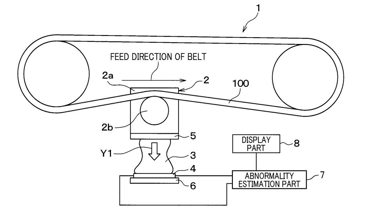
[0029]An abnormality estimation apparatus 1 according to a first embodiment of the invention is described with reference to FIGS. 1 to 6. The abnormality estimation apparatus 1 is an apparatus for estimating an abnormality in a belt 100 of a belt conveyor show in FIG. 1. FIG. 2 is a diagram showing the structure of the abnormality estimation apparatus 1 when the tension of the belt 100 starts to be measured. FIG. 3 is a diagram showing the structure of the abnormality estimation apparatus 1 when the tension of the belt 100 has increased thereafter. The abnormality estimation apparatus 1 includes a displacement part 2, an elastic body 3, a heat flow sensor 4, plate-like members 5 and 6, an abnormality estimation part 7 and a display part 8. The arrow Y1 in FIG. 2 shows the direction of displacement of the elastic body 3 at a time when the tension of the belt 100 has increased.

[0030]As shown in FIGS. 2 and 3, the plate-like member 6, the heat flow sensor 4, the elastic body 3, the pla...

second embodiment

[0059]Next a second embodiment of the invention is described with a focus on differences with the first embodiment referring to FIGS. 7 and 8.

[0060]In FIGS. 7 and 8, the abnormality estimation part 7 and the display part 8 are omitted from illustration. In FIG. 7, the arrow Y2 shows the direction of displacement of the displacement part 2 at a time when the tension of the belt 100 has changed, and the arrow Y3 in FIG. 7 shows the direction of displacement of the elastic body 3 at a time when the tension of the belt 100 has increased.

[0061]The abnormality estimation apparatus 1 of this embodiment includes, in addition to the displacement part 2, the elastic body 3, the heat flow sensor 4, the abnormality estimation part 7 and the display part 8, a case part 9 for supporting the elastic body 3, a support mechanism 10 which causes the case part 9 to support the displacement part 2, a radiator 11, and a plate-like member 12.

[0062]In this embodiment, the displacement part 2 rotates with ...

third embodiment

[0080]Next a third embodiment of the invention is described with a focus on differences with the first embodiment referring to FIGS. 9 and 10.

[0081]In FIGS. 9 and 10, the abnormality estimation part 7 and the display part 8 are omitted from illustration. In FIG. 9, the arrow Y4 shows the direction of displacement of the displacement part 2 at a time when the tension of the belt 100 has changed, and the arrows Y5 to Y8 show the directions of displacement of the elastic body 3 at a time when the tension of the belt 100 has increased.

[0082]In this embodiment, the displacement part 2 includes the proximal portion 2c and the roller portion 2d. As shown in FIGS. 9 and 10, the proximal portion 2c of the displacement part 2 includes a rod-shaped portion 2ca formed with the roller portion 2d at one distal end thereof and formed with a polyhedral portion 2cb at the other distal end thereof. In this embodiment, the polyhedral portion 2cb of the displacement part 2 has a cubic shape. The rod-sh...


PUM


Abstract

An abnormality estimation apparatus for estimating an abnormality in a belt of a belt conveyor includes a displacement part that is displaced in accordance with tension or a change of the tension of the belt when the displacement part is caused to abut against the belt to receive the tension of the belt, an elastic body that is elastically deformed in accordance with displacement of the displacement part, a heat flow sensor that detects a heat flow occurring due to elastic deformation of the elastic body, and an abnormality estimation part that estimates whether there is an abnormality in the belt based on a detection result by the heat flow sensor.

Description

[0001]This application claims priority to Japanese Patent Application No. 2016-81187 filed on Apr. 14, 2016, the entire contents of which are hereby incorporated by reference.BACKGROUND OF THE INVENTION1. Field of the Invention[0002]The present invention relates to an abnormality estimation apparatus for estimating abnormality in a belt of a belt conveyer.2. Description of Related Art[0003]In a belt conveyer apparatus for conveying hauls, if a belt of a belt conveyer is broken during its operation, the operation of the whole apparatus is stopped. Accordingly, it is important to periodically check the state of the belt (load, age deterioration, use period and so on).[0004]Japanese Patent Application Laid-open No. H9-133592 describes a life prediction apparatus for predicting a life of a belt. In this life prediction apparatus, a frictional slide workload is calculated as a parameter related to friction between the belt and a gear that rotates the belt based on geometric data, materia...

Claims


Application Information

Patent Timeline
IPC IPC(8): G01B21/32G01N25/20B65G43/00
CPCG01B21/32B65G43/00G01N25/20B65G43/02G01N25/18G01N25/72
Inventor GOUKO, NORIOTANIGUCHI, TOSHIHISASAKAIDA, ATUSIOKAMOTO, KEIJISHIRAISHI, YOSHIHIKOASANO, MASAHIRO
Owner DENSO CORP