

Projection device and method for projecting at least one image onto a projection surface
- Summary
- Abstract
- Description
- Claims
- Application Information
AI Technical Summary
Benefits of technology
Problems solved by technology
Method used
Image

Examples
Embodiment Construction
[0011]It is the object of the present invention to provide a projection device that operates an AC-operated discharge lamp in such a way that the lifetime performance is improved in a particularly simple manner.
[0012]This object is achieved by a projection device with the features of claim 1 and by a method with the features of claim 17. Further advantageous embodiments emerge from the subsidiary claims.
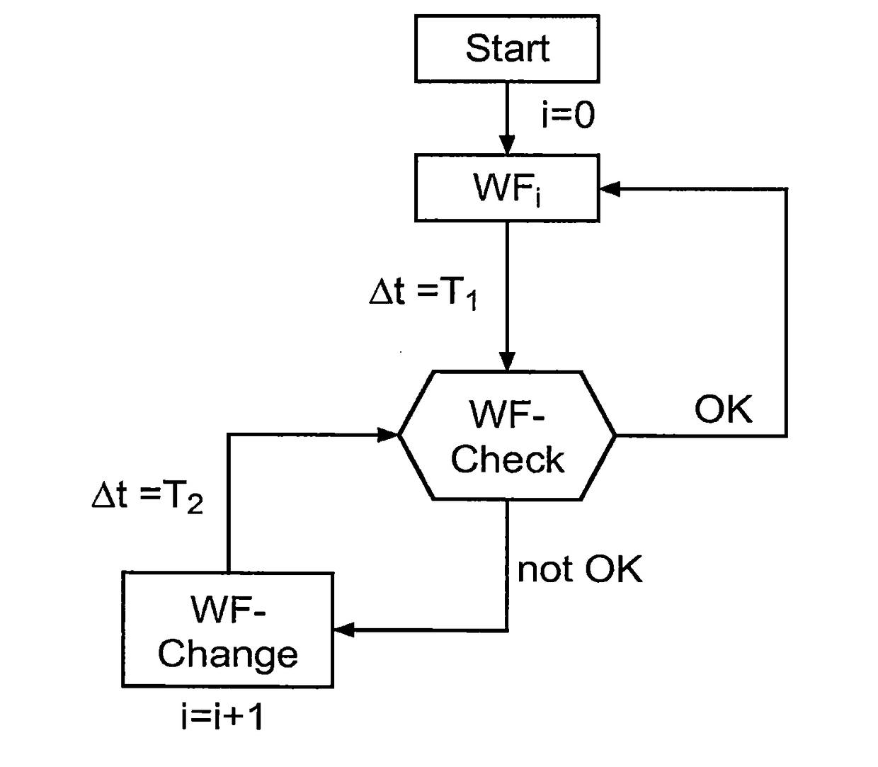
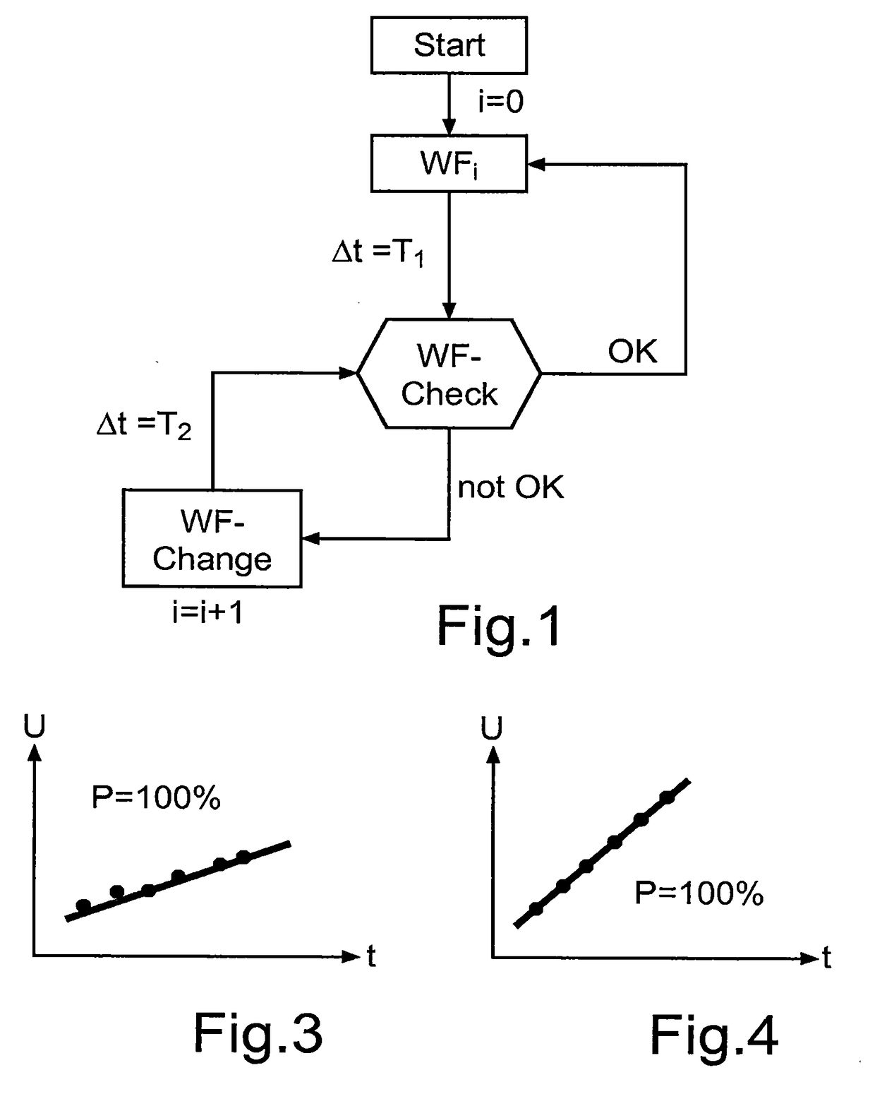
[0013]According to the invention, a generic projection device is further developed in such a way that the control device is designed, on the basis of an evaluation of at least one measured value of the measuring device determined during a drive of the discharge lamp with a current waveform to be checked, to check the current waveform in respect of its suitability for minimizing an electrode burn-back of the first electrode and the second electrode, and in the case of a positive check result to retain the checked current waveform, and in the case of a negative check result, depending ...
PUM
 Abstract
Description
Claims
Application Information