
Boiler for steam mop
- Summary
- Abstract
- Description
- Claims
- Application Information
AI Technical Summary
Benefits of technology
Problems solved by technology
Method used
Image

Examples
Embodiment Construction
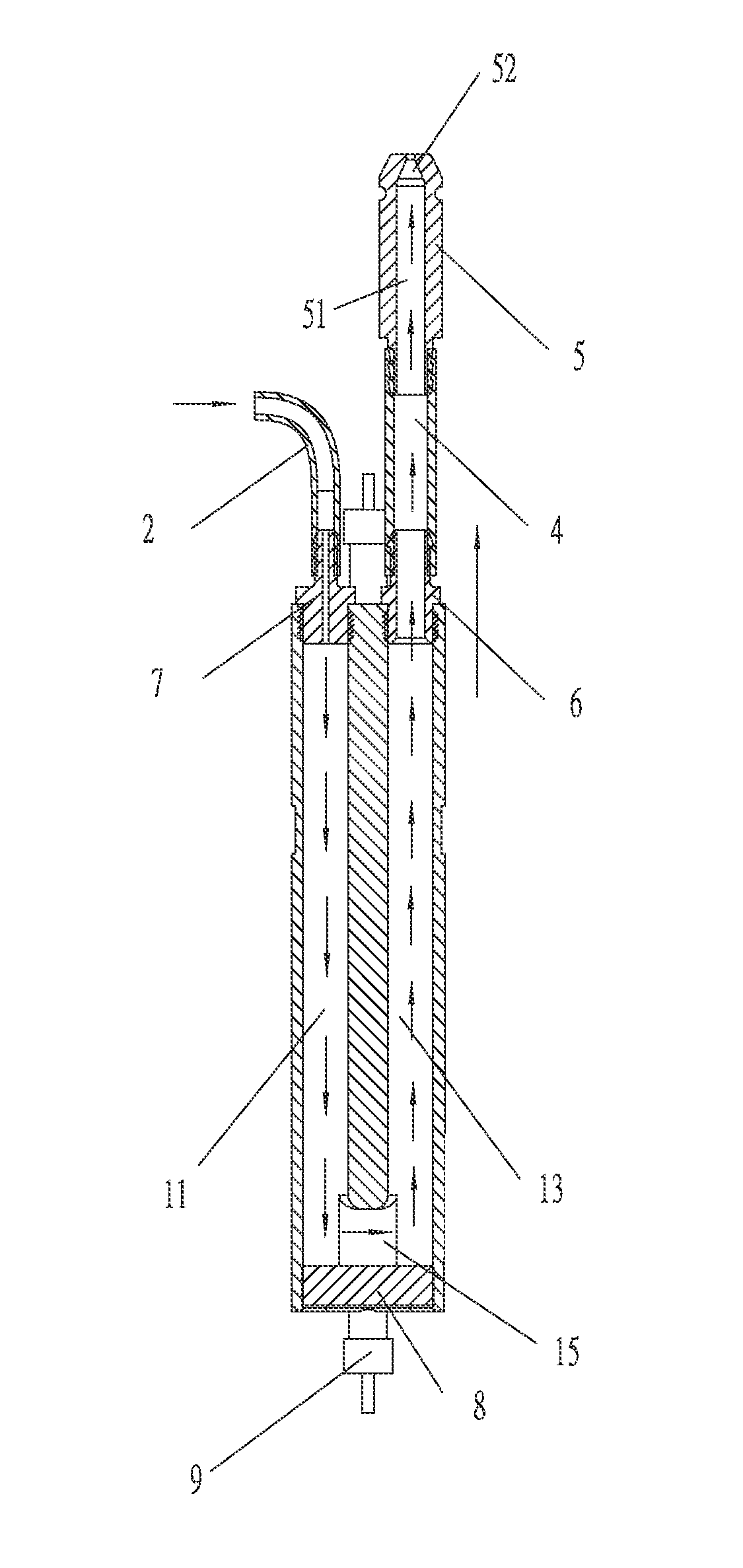
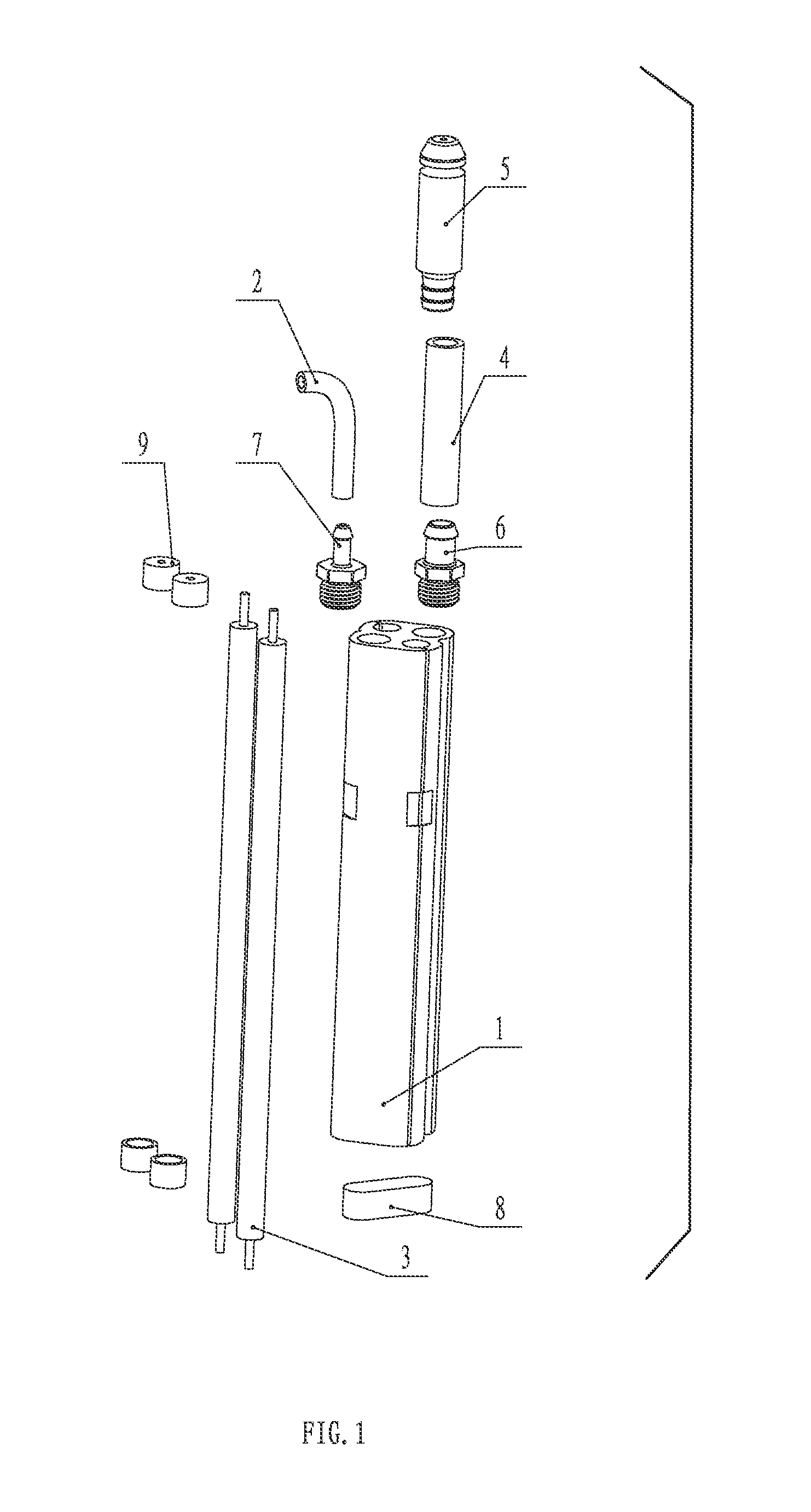
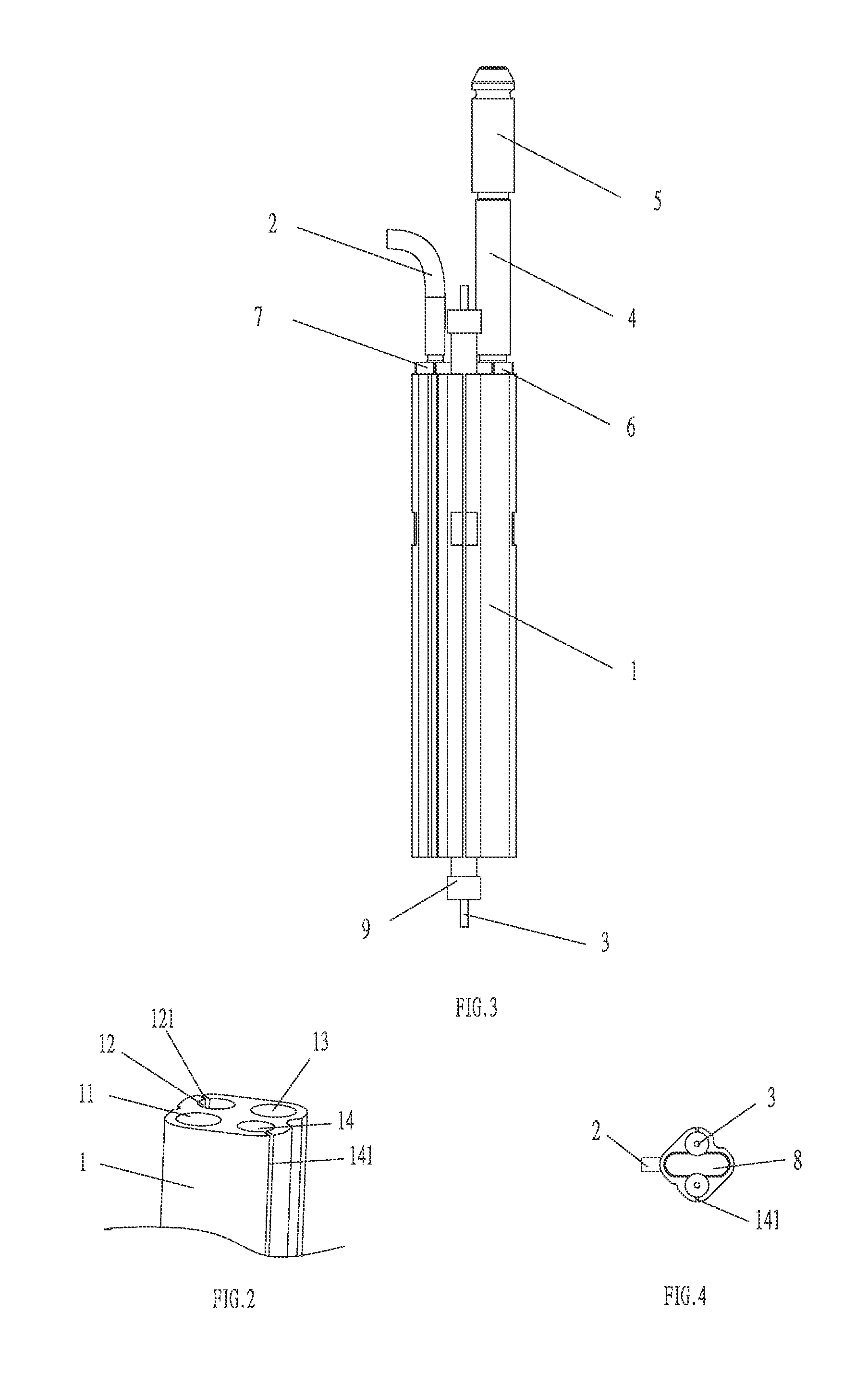
[0030]Refer to the FIG. 1 to the FIG. 6. The detailed embodiment of the present invention of a boiler for a steam mop includes a boiler 1, a water inlet pipe 2, a heating element 3, a steam pipe 4 and a steam nozzle 5.
[0031]The boiler 1 is cuboid shaped, and four holes are disposed inside along the length direction. Two holes 11 and 13 in the diagonal position are disposed as the liquid way, while another two holes 12 and 14 in another diagonal position are disposed as the way for the heating element 3. The holes 12 and 14 are separately disposed with a crack 121 and 141 on the wall for the material of expanding when heated and contracting when cooled. Two ends of the heating element 3 are separately extended out of the two ends of the boiler 1 and insulated by silica gel cap 9. A cover 8 is disposed in the lower of the boiler 1 to close the two holes 11 and 13. A lateral hole 15 is disposed inside the boiler 1 beside the cover 8 to connect the two holes 11 and 13. The holes 11, 13 ...
PUM
 Abstract
Description
Claims
Application Information