
Gate Valve In Which Amount Of Squeeze Of Sealing Material Is Controllable

Active Publication Date: 2013-11-21
V TEX
View PDF2 Cites 3 Cited by
  • Summary
  • Abstract
  • Description
  • Claims
  • Application Information

AI Technical Summary

Benefits of technology

The present invention provides a gate valve that can control the amount of sealing material used based on manufacturing or vacuum-maintenance situations. This helps to prevent deterioration of the sealing material and extends its lifespan.

Problems solved by technology

With this, the reduced amount of squeezing of a sealing material during the in-manufacturing will suppress the deterioration of the sealing material and lengthens its service life.
In the gate valves of above stated patent literatures however, the amount of squeeze of the sealing material is not controlled whether under the in-manufacturing.

Method used


Image

  • Gate Valve In Which Amount Of Squeeze Of Sealing Material Is Controllable
  • Gate Valve In Which Amount Of Squeeze Of Sealing Material Is Controllable
  • Gate Valve In Which Amount Of Squeeze Of Sealing Material Is Controllable

Examples


embodiment 1

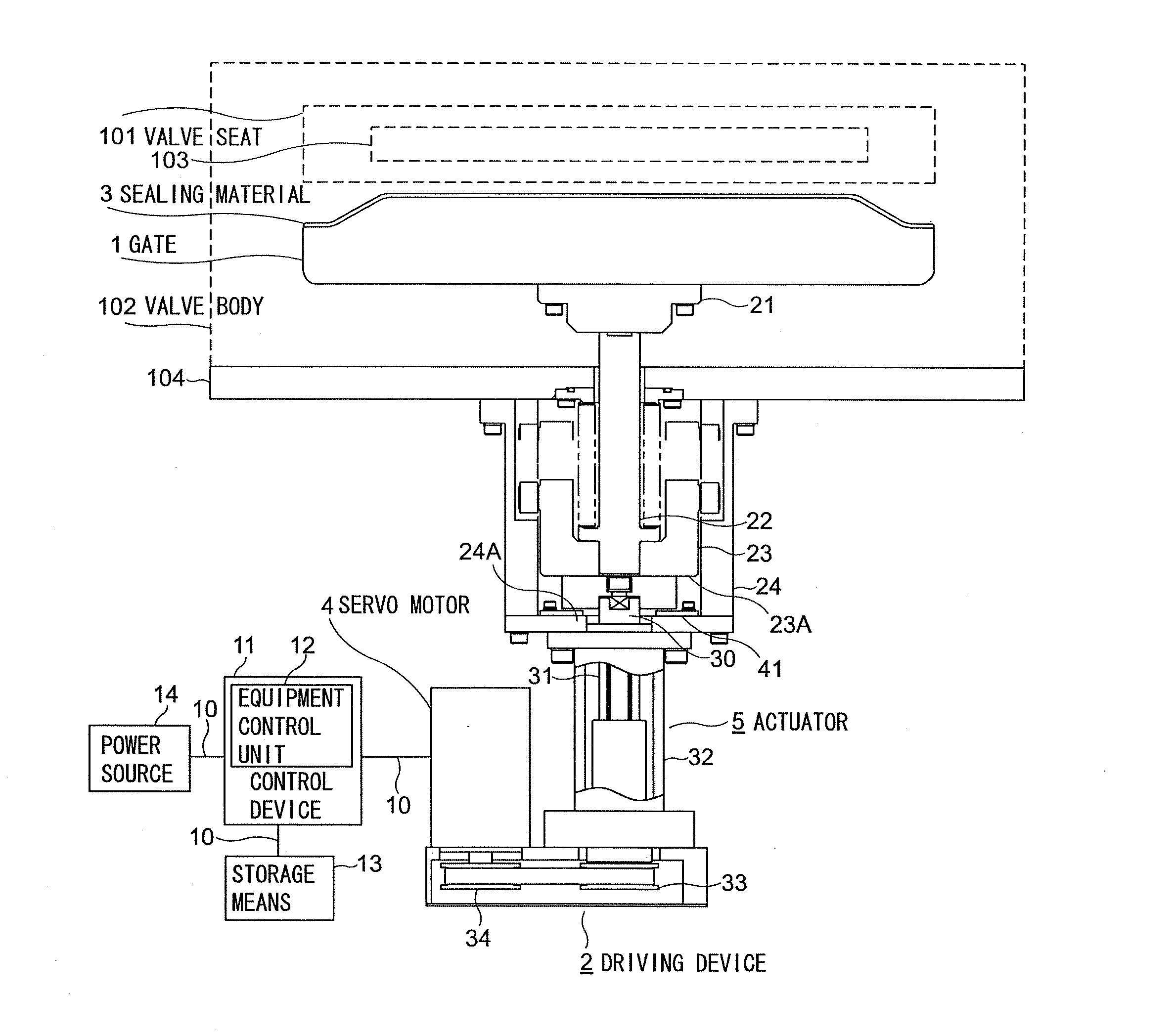
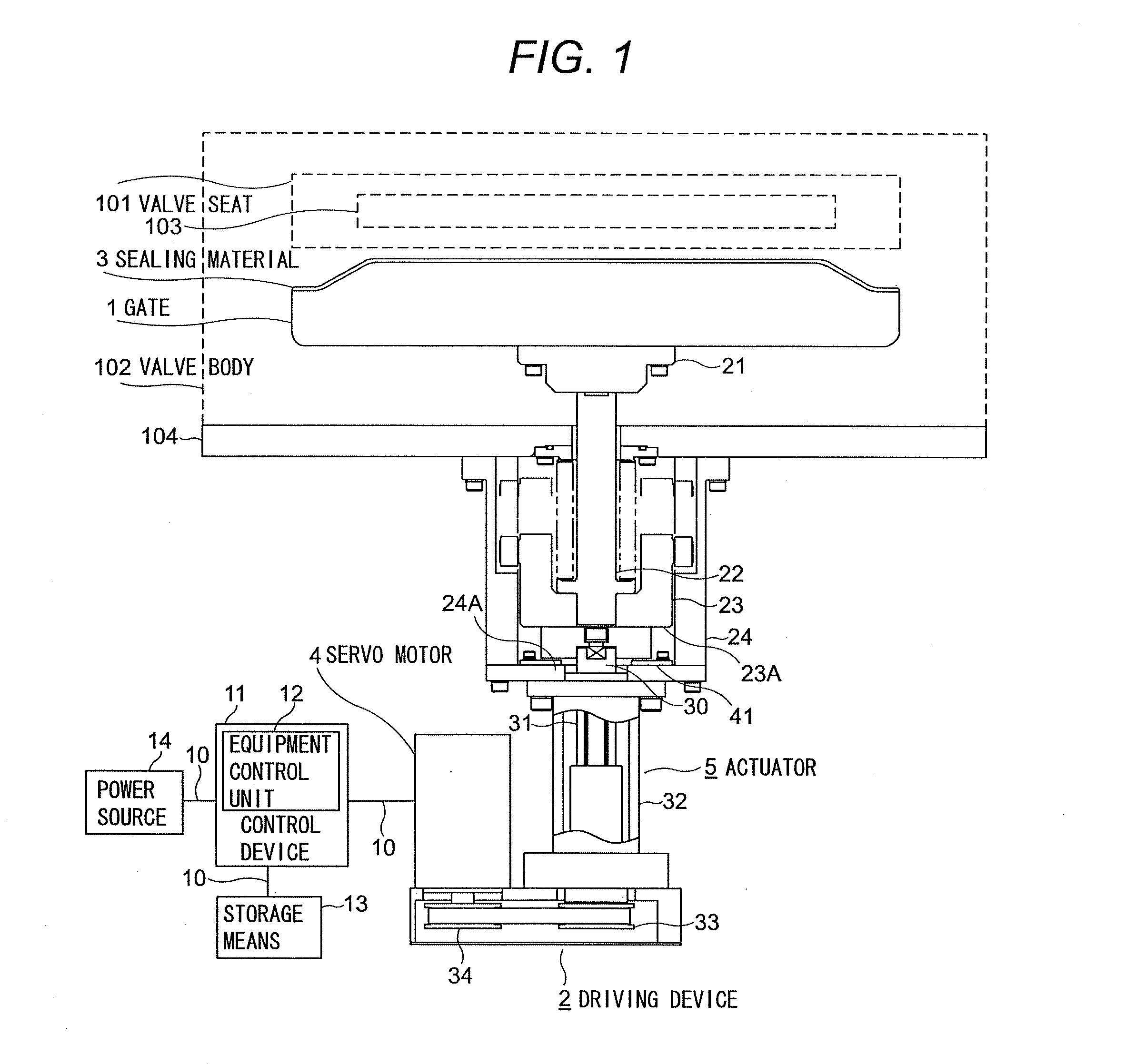
[0074]The following explains a gate valve of an embodiment of the present invention referring to FIG. 1, which is a schematic diagram that illustrates the gate valve of the embodiment.

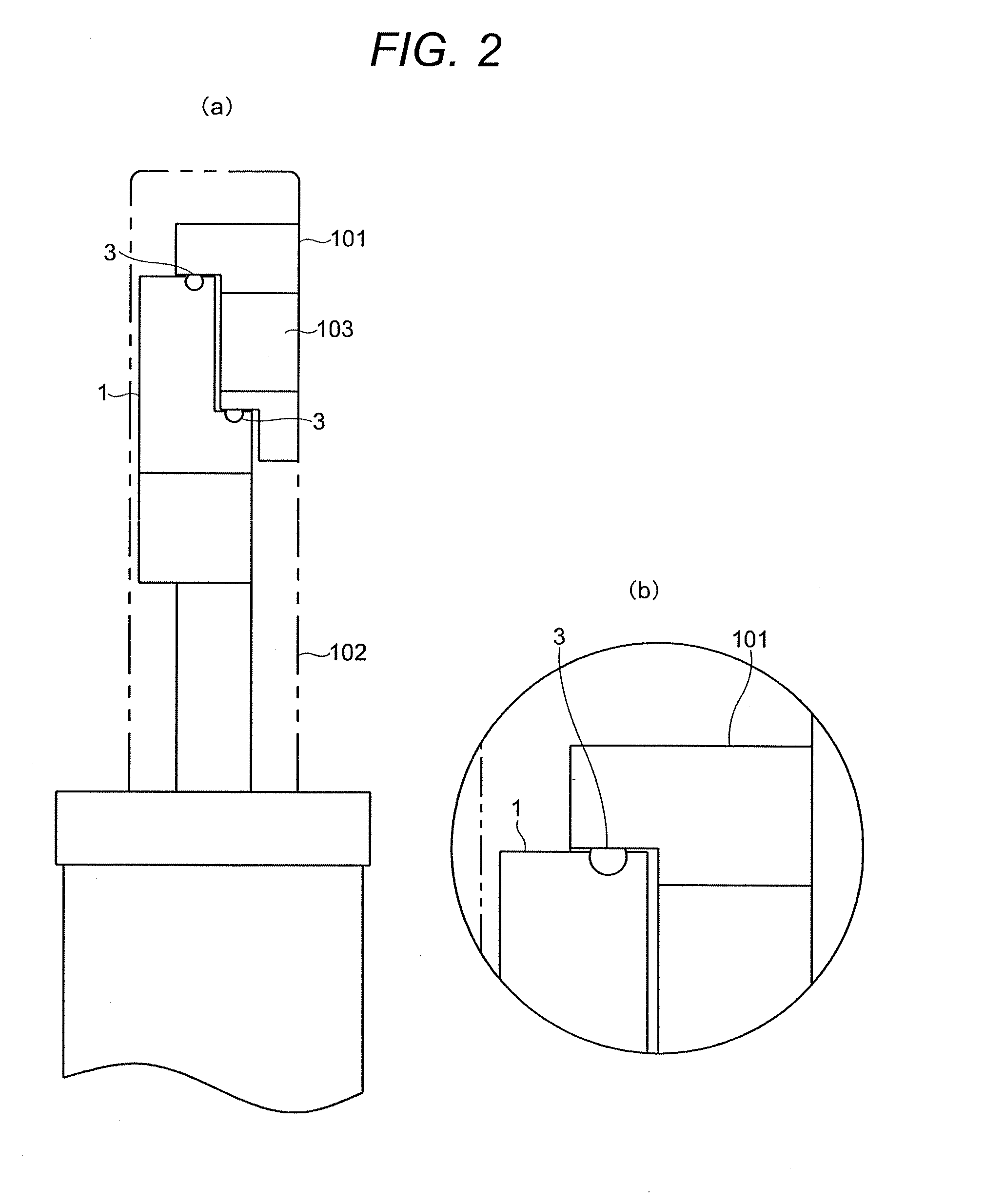
[0075]A gate valve 100 of the embodiment has a valve seat 101 and a gate 1 arranged confronting the valve seat 101. The gate 1 is driven by a driving device 2 to the valve seat 101 to press and squeeze a sealing material 3 against the valve seat 101. Being squeezed, the sealing material 3 seals gas that passes through an opening 103 on the valve seat 101.

[0076]The driving device 2 is comprised of a servo motor 4 and an actuator 5 that translates the rotative force from the servo motor 4 into a linear-motion to drive the gate 1. The actuator 5 connects to the gate 1.

[0077]The driving device 2 is connected to a control device 11 via a communication means 10. The control device 11 connects, via the communication means 10, to each of a storage means 13 and a power source 14.

[0078]The control device 11 has ...


PUM


Abstract

{Summary}{Technical Problem} To provide a gate valve that can control the amount of squeeze of sealing material according to each of situations, that is, under the in-manufacturing or during vacuum-maintaining state; thereby, the invented gate valve is capable of suppressing deterioration of its sealing material and lengthening the service life of the sealing material used therein.{Solution to Problem} The gate valve 100 of the embodiment has the control device 11, which is comprised of the equipment control unit 12 that transmits an instruction either an in-manufacturing CLOSE instruction or a FULL CLOSE instruction and the storage means 13 that stores position date that corresponds to each of such instructions. The control device 11 receives either of such instructions and generates the position signal referring to the corresponding position data. The servo motor 4 of the driving device 2 receives the position signal and the rotative force of the servo motor 4, which corresponds to the received position signal, is translated into the movement of the activator 5. The sealing material 3 on the gate 1 is pressed against the valve seat 101 by the gate 1 driven according to each of the instructions and is maintained in the squeezed state.

Description

TECHNICAL FIELD[0001]The present invention relates to a gate valve that electrically opens and closes. The invention is applicable particularly to a gate valve in which the amount of squeeze of sealing material is controllable.BACKGROUND ART[0002]To date, gate valves of various types of mechanisms have been proposed for use in maintaining the vacuum of a vacuum chamber of such as semiconductor manufacturing equipment.[0003]For example, Patent literature 1 describes a gate valve. The gate valve described there has a housing having a gas passage. The housing accommodates a round-shaped valve plate (valve body); and to the housing, a driving device is attached. The driving device has a shaft that connects to the valve plate and an actuator that drives the shaft. The driving device linearly moves the valve plate to open or close the gas passage. The gate valve in that disclosure is, for instance, installed between a vacuum chamber and a vacuum pump in a semiconductor manufacturing equip...

Claims


Application Information

Patent Timeline
IPC IPC(8): F16K25/00F16K39/04
CPCF16K25/00F16K39/04F16K3/0254F16K51/02F16K3/02F16K3/16F16K37/00F16K3/18
Inventor NAGAI, HIDEAKIARAKI, SHUICHITADOKORO, TAKAYUKIYAMAGUCHI, NAOMICHI
Owner V TEX
Learn More