Suspension device

Inactive Publication Date: 2012-07-19
TOYOTA JIDOSHA KK +1
View PDF17 Cites 5 Cited by
  • Summary
  • Abstract
  • Description
  • Claims
  • Application Information

AI Technical Summary

Benefits of technology

[0010]According to the suspension device of the present invention, with the bearing interposed between a member coupled to one of the vehicle body and the vehicle axle, and an outer cylinder coupled to the other one of the vehicle body and the vehicle axle and arranged at the outer circumference of the member, smooth uninterrupted extension-retraction operation is ensured with the bearing generating substantially no friction force to resist against the extension-retraction of the suspension device, and additionally, lateral force does not act on the motion conversion mechanism; therefore, the motion conversion mechanism is protected and deterioration is suppressed, whereby smooth motion conversion is maintained over a long period of time.
[0011]More specifically, since the bearing is interposed between the outer cylinder, which is provided to one of the actuator and the fluid pressure damper, and the other one of the actuator and the fluid pressure damper, smooth uninterrupted extension-retraction operation is ensured with the bearing generating substantially no friction force to resist against the extension and retraction of both the actuator and the fluid pressure dampe

Problems solved by technology

However, this suspension device interposes an annular bearing in two parts between an outer cylinder for guiding linear motion of a motor and covering the motor, and the motor; therefore, even when attempting to absorb high frequency oscillations with the springs sandwiching the hydraulic damper and motor, it becomes difficult for the hydraulic damper to work due to the presence of the above-mentioned bearing, which hinders the oscillation absorbance, whereby vehicle ride quality may deteriorate from the oscillations transmitted to the spring upper member.
Furthermore, in this suspension device, forces from a lateral direction may be input due to changes in the geometry while the vehicle is travelling or the like, and since a structure is made that receives this force at the threaded region o

Method used


Image

  • Suspension device
  • Suspension device
  • Suspension device

Examples


Example

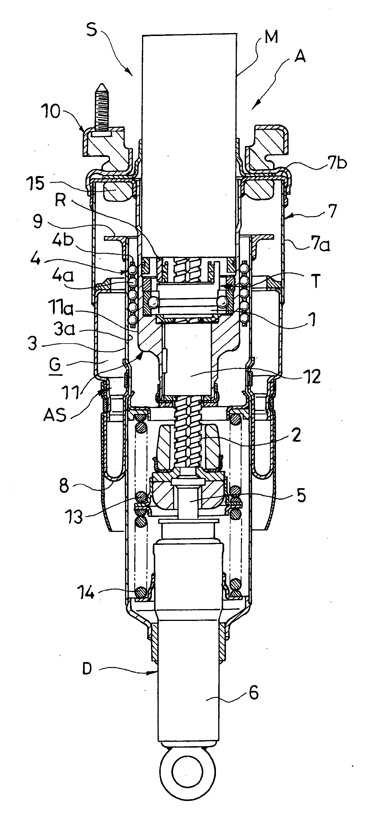
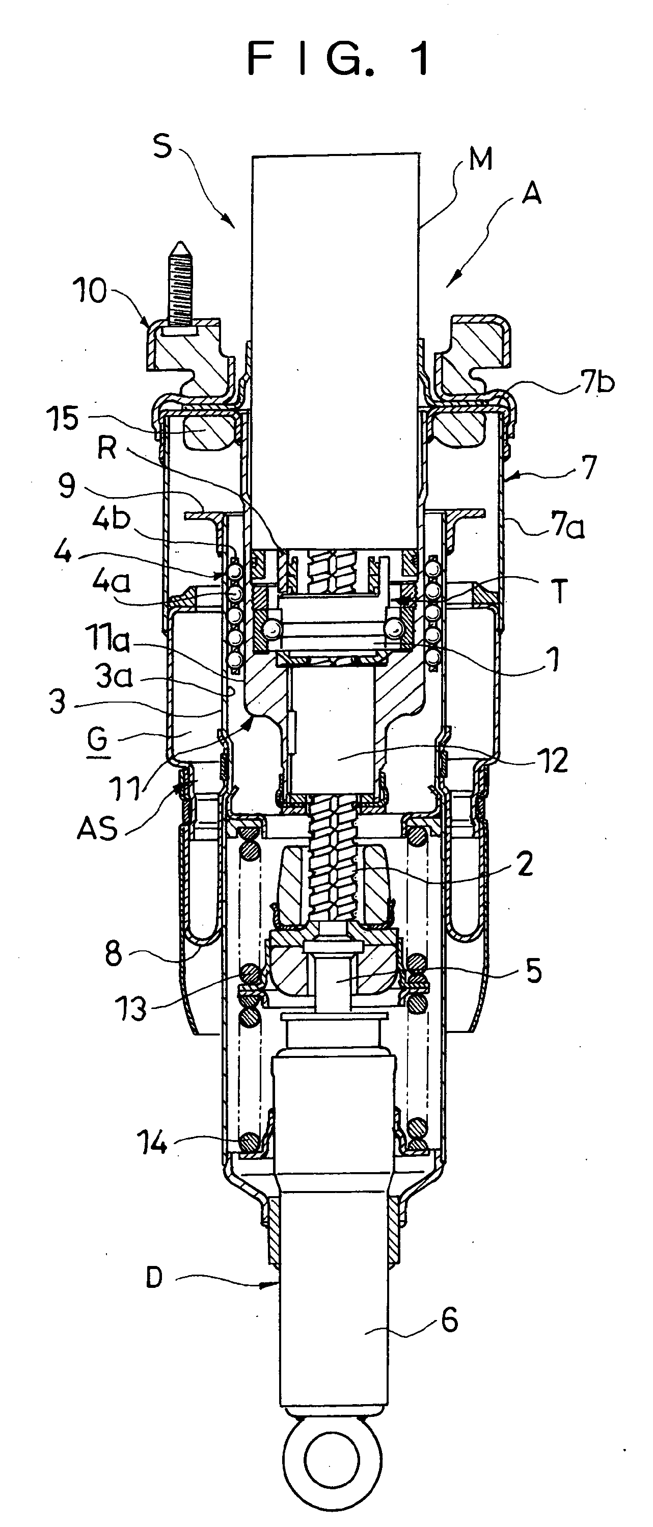
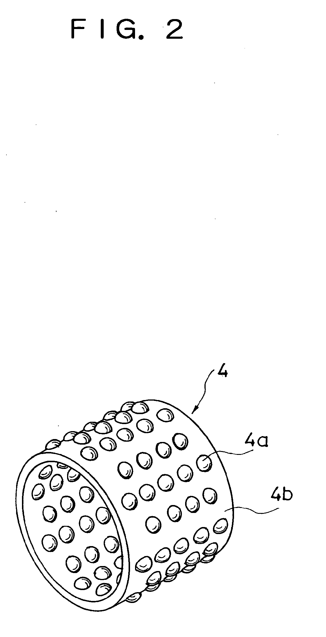
[0017]Hereinafter, the present invention will be explained based on the embodiments illustrated in the drawings. As shown in FIG. 1, a suspension device S according to one embodiment includes: an actuator A equipped with a motion conversion mechanism T that converts linear motion into rotational motion, and a motor M that is coupled to a ball screw nut 1 serving as a rotational member that exhibits the rotational motion of the motion conversion mechanism T; a fluid pressure damper D having a rod 5 and a damper main body 6 into which the rod 5 moves in and out; an outer cylinder 3 that is provided to the damper main body 6 and is disposed at the outer circumference of the actuator A; and a bearing 4 interposed between the outer cylinder 3 and the actuator A; the device being configured to connect a threaded shaft 2 serving as a linear motion member that exhibits the linear motion of the motion conversion mechanism T to the rod 5 of the fluid pressure damper D.

[0018]In addition, in th...


PUM


Abstract

A suspension device (S) of the present invention includes: a member (11) coupled to one of a vehicle body and a vehicle axle; an outer cylinder (3) coupled to the other one of the vehicle body and the vehicle axle and disposed at the outer circumference of the member (11); and a bearing (4) that is interposed between the member (11) and the outer cylinder (3), the bearing (4) having balls (4a) that rollably contact at least one of the member (11) and the outer cylinder (3), and a ball case (4b) that retains the balls (4a) rollably.

Description

FIELD OF THE INVENTION[0001]The present invention relates to an improvement in a suspension device that suppresses relative movement between a vehicle body and vehicle axle using the electromagnetic force generated in a motor.DESCRIPTION OF THE RELATED ART[0002]As this type of suspension device, Japanese Patent Application Laid-Open No. H08-197931 discloses, for example, a device that is configured by a suspension spring elastically supporting a vehicle body, i.e. spring upper member of a vehicle; an actuator including a threaded shaft rotatably threaded to a ball screw nut coupled to a vehicle axle, i.e. spring lower member, and a motor that is coupled to one end of the threaded shaft and is elastically supported to the spring upper member by being interposed between a pair of springs; and a hydraulic damper fixed to the spring upper member and dampening oscillations in the vertical direction of the actuator, and this device carries out active control of the relative movement betwe...

Claims


Application Information

Patent Timeline
IPC IPC(8): B60G11/30F16C19/04
CPCB60G17/0157B60G17/02B60G2204/418F16F9/16F16F2232/06F16C29/04F16C33/32F16C33/40B60G2202/32B60G2202/42F16F2232/04F16F9/366F16C2326/05
Inventor KONDO, TAKUHIROHIROSE, MITSUHIKOTACHI, TAKAYUKIFUKUMOTO, YASUTAKAHONMA, MOTOHIKO
Owner TOYOTA JIDOSHA KK
Why Eureka
Try Eureka