This helps you quickly interpret patents by identifying the three key elements:
Problems solved by technology
Method used
Benefits of technology
Benefits of technology
[0056] According to the present invention, a fuel cell having excellent durability that can suppress deterioration of the polyelectrolyte membrane, and maintains high voltage over a long period of time can be provided.
Problems solved by technology
However, in general, when a fuel cell is used as a power source, several to several hundreds of volts is required.
Method used
Image
Click on the blue label to locate the original text in one second.
Reading with bidirectional positioning of images and text.
Examples
example 1
[0117] At first, Pt volume density in the respective catalyst layer 102 of the anode 109 and the cathode 110 was changed, and while maintaining the Pt volume density in the catalyst layer 102 of the cathode 110 constant, the catalyst layer thickness of the cathode 110 was investigated by changing the coating amount of the catalyst.
[0118] Where Pt density in the catalyst layer 102 of the anode 109 was 5 and 6 g / cm3, catalyst layers were prepared using Pt powder having a size of crystallite of 10 and 15 nm. Further, where Pt density was 0.8 and 1 g / cm3, they were prepared by adding 5 and 6% of a carbon powder (conductive carbon fine particles) to Pt powder of 10 nm, respectively.
[0119] As the catalyst layer 102 of the cathode 110, catalysts having a mixing weight % to Pt of the carbon powder of 80, 70, 15 and 10% were used to Pt volume density of 0.6, 0.5, 0.1 and 0.08 g / cm3, respectively, and the coating amount was adjusted to change the thickness.
[0120] Further, investigations we...
example 2
[0128] Investigations were made on composition of the conductive carbon fine particles and the catalyst fine particles in the catalyst layer, and the mixing ratio of the catalyst fine particles and the polyelectrolyte in the catalyst layer of the anode 109. The mixing ratio of Pt fine particles and a ketjen black used as the conductive carbon fine particles was changed to 0, 5 and 7% in the catalyst of the anode 109, and to the respective embodiment, the mixing ratio of Pt fine particles and ketjen black was changed to 25, 30, 60 and 65% in the catalyst layer 102 of the cathode 110.
[0129] The amount of the conductive resin added to the catalyst layer 102 of the anode 109 was adjusted such that the ratio of weight of a catalyst (the sum of Pt or Pt alloy catalyst and carbon) and weight of an electrolyte resin (Wpoly / Wcat) was 0.02, 0.03, 0.3 and 0.35%. Further, the catalyst amount was adjusted such that 0.7 mg of Pt per 1 cm2 of the catalyst layer 102 was held in both the anode 109 ...
example 3
[0137] In Table 7, regarding the electrode catalyst of the catalyst layer 102 of the cathode 110, Pt particles and conductive carbon fine particles were not mixed, and the electrode catalyst in which Pt particles are carried on the conductive carbon fine particles was used.
[0138] It is considered that by having Pt particles carried on the conductive carbon fine particles, Pt particles are further finely divided, and activity of the catalyst improves.
TABLE 7Pt carrying CWeight ratio ofPt volumePt volumecatalyst (Ptdensitydensitycatalyst + carbon)ThicknessFluoridein anodein cathodeand electrolyteof anodeAlloy fineionDischargecatalystcatalystresin in anodecatalystparticleDischargedischargevoltagelayerlayercatalyst layerlayerdiametervoltagerateratiog / cm3g / cm3%μmnmmVμg / day / cm2Uf20.40.150.56nm7300.379710nm7250.419715nm7220.459516nm7450.129810nm7420.179715nm7350.199656nm7480.119710nm7440.159515nm7400.189476nm7480.119410nm7450.159115nm7420.1989
[0139] From the test result, improvement in ...
PUM
Abstract
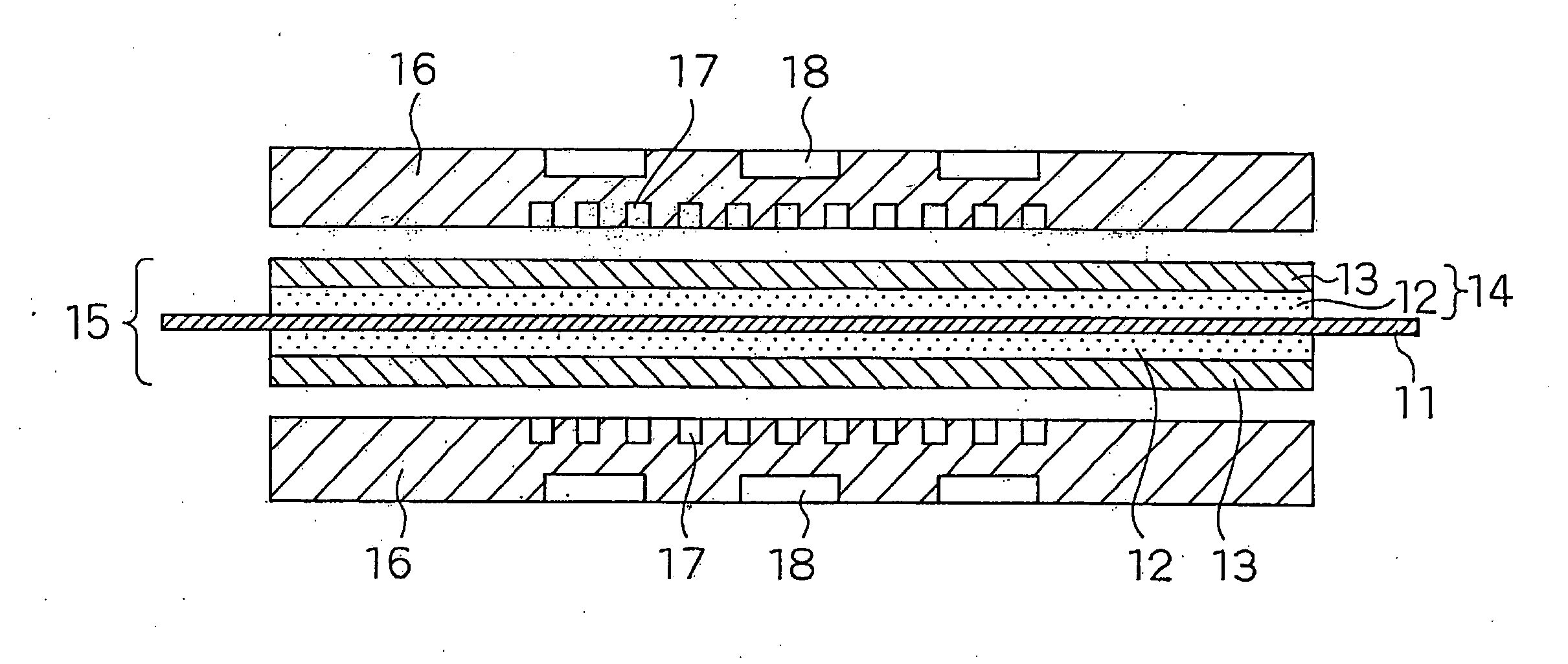
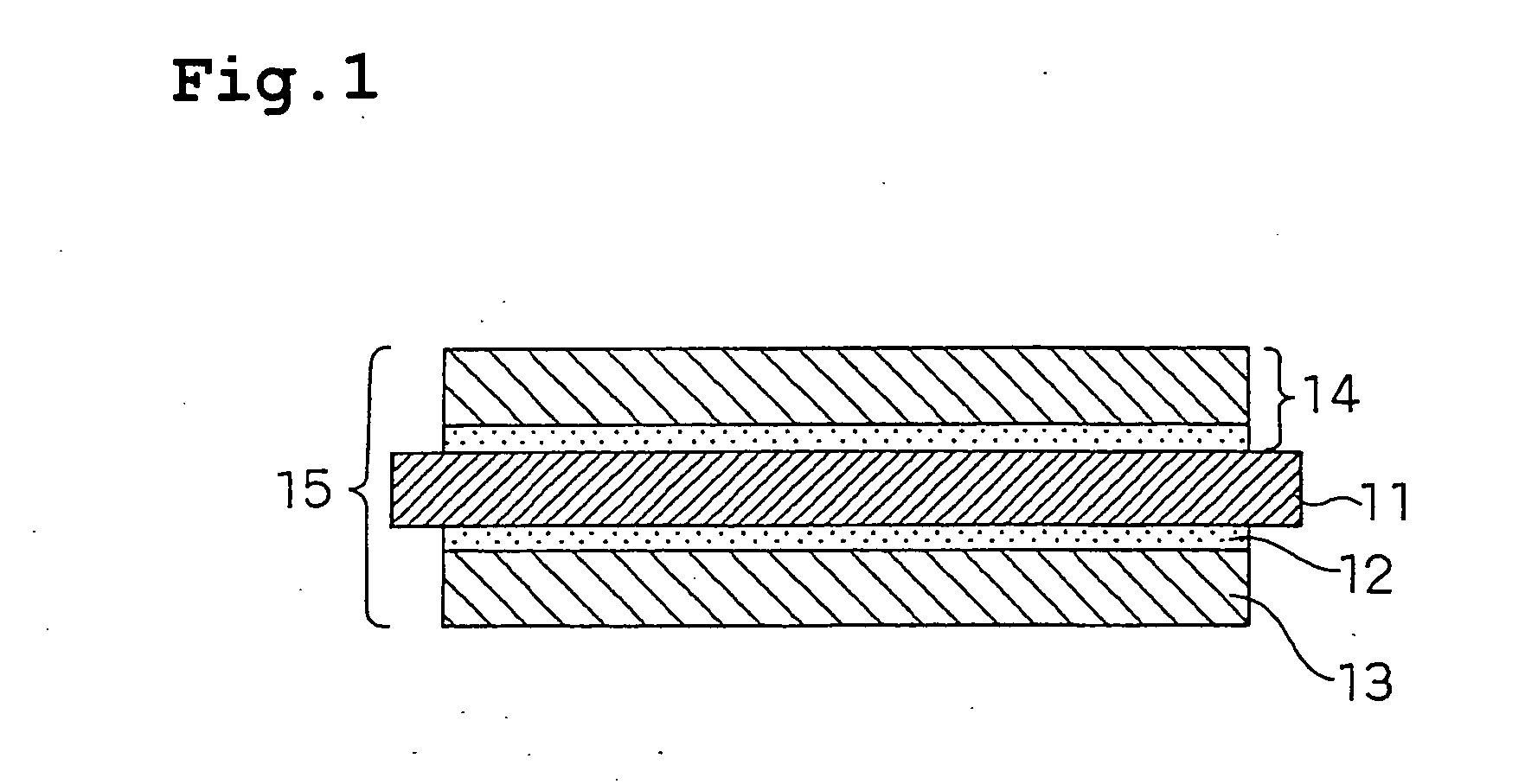
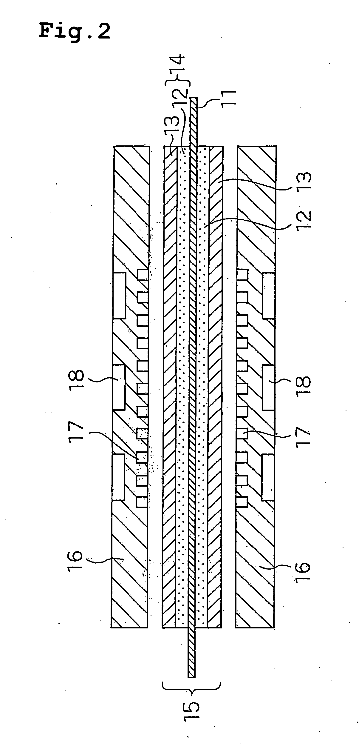
A solidpolymerelectrolyte fuel cell includes a membrane electrode assembly having an anode, a cathode arranged facing the anode, and a polyelectrolyte membrane arranged between the anode and the cathode, and a pair of separator plates that are arranged facing each other so as to sandwich the membrane electrode assembly, and have an anode side gas channel for supplying a fuel gas to the anode, and a cathode side gas channel for supplying an oxidant gas to the cathode, formed thereon, wherein the catalyst layer of the anode contains at least one electrode catalyst selected from the group consisting of Pt particles and Pt alloy particles, having a particle diameter of from 6 to 10 nm, the catalyst layer of the anode has a thickness of from 1 to 5 μm, Pt volume density in the catalyst layer of the anode is from 1 to 5 g / cm3, the catalyst layer of the cathode has a thickness of 10 μm or more, and Pt volume density in the catalyst layer of the cathode is from 0.1 to 0.5 g / cm3.
Description
CROSS-REFERENCE TO RELATED APPLICATIONS [0001] This application is a U.S. national phase application of PCT International Patent Application No. PCT / JP2005 / 012866 filed Jul. 12, 2005, claiming the benefit of priority of Japanese Patent Application No. 2004-206128 filed Jul. 13, 2005, all of which are incorporated by reference herein in their entirety.TECHNICAL FIELD [0002] The present invention relates to a polymerelectrolyte fuel cell that has designed to suppress deterioration or improve durability, of its polyelectrolyte membrane. BACKGROUND ART [0003] General constitution of a conventional polymerelectrolyte fuel cell stack is explained. [0004] A fuel cell using a polyelectrolyte simultaneously generates electric power and heat by electrochemically reacting a fuel gas containing hydrogen and an oxidant gas containing oxygen, such as air. FIG. 5 is a schematic cross-sectional view for explaining the structure of a unit cell of a solid polymer electrolyte fuel cell. As shown in ...
Claims
Application Information
Patent Timeline
Application Date:The date an application was filed.
Publication Date:The date a patent or application was officially published.
First Publication Date:The earliest publication date of a patent with the same application number.
Issue Date:Publication date of the patent grant document.
PCT Entry Date:The Entry date of PCT National Phase.
Estimated Expiry Date:The statutory expiry date of a patent right according to the Patent Law, and it is the longest term of protection that the patent right can achieve without the termination of the patent right due to other reasons(Term extension factor has been taken into account ).
Invalid Date:Actual expiry date is based on effective date or publication date of legal transaction data of invalid patent.

