
Method And System For Controlling And/Or Regulating The Treatment Of Heat-Sensitive Liquid Food Products

Active Publication Date: 2020-05-14
GEA TDS
View PDF0 Cites 1 Cited by
  • Summary
  • Abstract
  • Description
  • Claims
  • Application Information

AI Technical Summary

Benefits of technology

The patent is about a method, system, and pump for controlling and regulating the treatment of sensitive liquid food products. The pump used in the system is modified to prevent the growth of product fouling and increase its lifespan. The technical effects of this patent include improved fill level regulation and constant dwell time of the liquid food product, inhibited growth of product fouling, and increased lifespan of the pump.

Problems solved by technology

Product fouling reduces the service life, or respectively the operating time of the infuser container and in particular the centrifugal pump between two cleaning cycles.
The rotating displacement pump is generally arranged directly at the outlet opening because unproblematic regulation of a desired minimum fill level in the infuser container is possible due to the specific rotary-speed-dependent volumetric flow of this pump type.
A fluctuating fill level in the bottom region of the infuser container leads to an undesirable and undefined dwell time at that location; a lowering of the fill level to the entrance of the centrifugal pump can cause vapor to be sucked into the centrifugal pump and hence can cause undesired cavitation.
Undefined dwell times and cavitation cause a reduction in the quality of the liquid food product.
However, a centrifugal pump is also claimed without indicating how this centrifugal pump is designed.
For example, when directly heating very heat-sensitive liquid food products in an infuser container and then discharging the heated liquid food products out of the infuser container by means of a downstream centrifugal pump of the usual design, i.e., hydraulically optimized design, it was revealed that this centrifugal pump becomes clogged within a very short time, that is, clogged within seconds to a few minutes, by product fouling, and therefore stops operating.
A satisfactory solution remains unknown for the specific design of a centrifugal pump in a system for treating heat-sensitive liquid food products in which the latter undergo direct heating by means of culinary steam.
With this type of control and / or regulation, it was revealed that fill level fluctuations in the drainpipe unavoidably occur and cannot be prevented.
If the fill level is too high, then the exposure time of the liquid food product to the steam is insufficient with this necessarily reduced drop height, the desired product temperature setpoint is not reached, and vapor bubbles inclusions remain in the insufficiently heated liquid food product.
If a fill level is too low, on the one hand the product temperature setpoint is exceeded, and on the other hand the danger exists of vapor being sucked into the centrifugal pump which can produce cavitation there with harmful consequences to the liquid food product and the centrifugal pump.
Vapor bubble inclusions from fluctuations in the fill level and hence dwell time lead to increased product fouling, in particular on the blades of the centrifugal pump.
Product fouling generally causes a shortening of the operating phase of the system, wherein the duration of the operating phase is also termed the service life of the system.
Cooling these regions causes a lengthening of the service life but cannot prevent product fouling on the blades of the centrifugal pump; instead, it can only inhibit the growth of product fouling.
This product fouling necessarily yields a reduction of the throughput of the centrifugal pump because passage cross-sections constrict, and friction resistances in the regions of the flow close to the wall increase, which further enhances the fill level fluctuations and hence dwell time fluctuations in the relevant parts of the system which are already problematic.

Method used


Image

  • Method And System For Controlling And/Or Regulating The Treatment Of Heat-Sensitive Liquid Food Products
  • Method And System For Controlling And/Or Regulating The Treatment Of Heat-Sensitive Liquid Food Products
  • Method And System For Controlling And/Or Regulating The Treatment Of Heat-Sensitive Liquid Food Products

Examples


Embodiment Construction

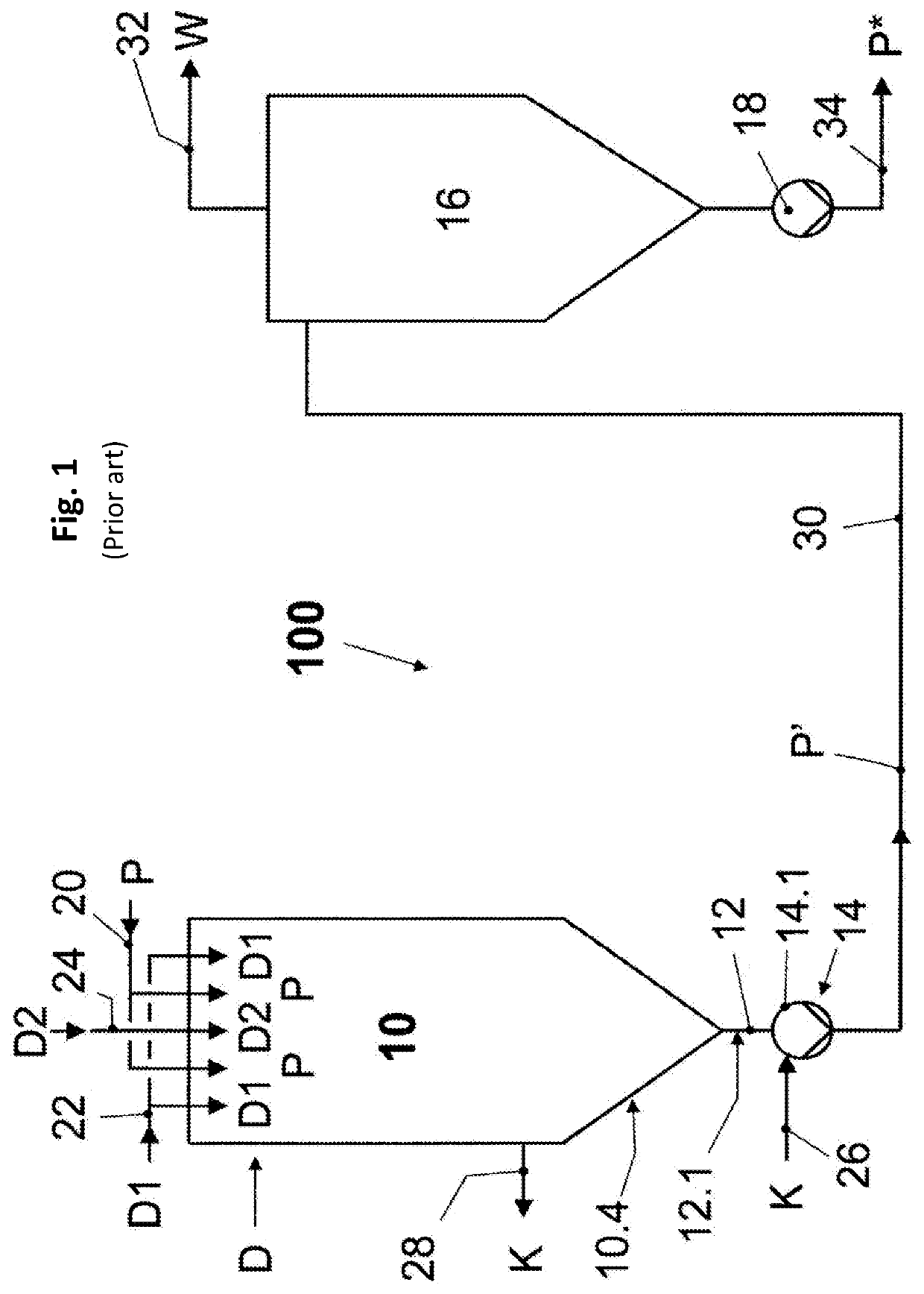
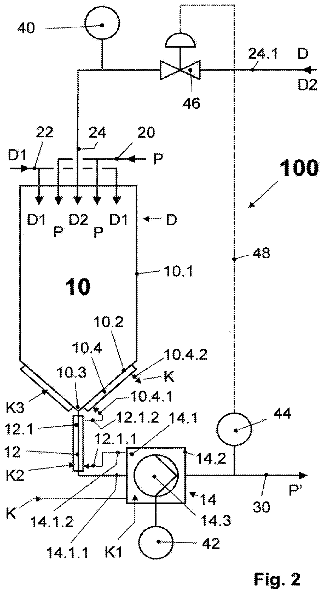
[0059]A system 100 known from the prior art according to FIG. 1 (such as WO 2016 / 012026 A1) contains an infuser container 10 as described for example in WO 2010 / 086082 A1 and that has a product inlet 20 in its headspace through which a liquid food product P that is to be heat-treated is supplied to this infuser container 10 centrally and annularly. The liquid food product P supplied in this manner is also supplied with steam D for direct heating through the headspace of the infuser container 10, namely a first steam D1 radially from the outside through an external steam inlet 22, and a second steam D2 radially from the inside through an internal steam inlet 24.

[0060]The infuser container 10 is bordered at its bottom tapering downward toward an outlet opening by a container-bottom-side coolant chamber 10.4. The outlet opening of the infuser container 10 is connected by a drainpipe 12 that is surrounded by a drainpipe-side coolant chamber 12.1 to a first delivery apparatus 14 that is ...


PUM


Abstract

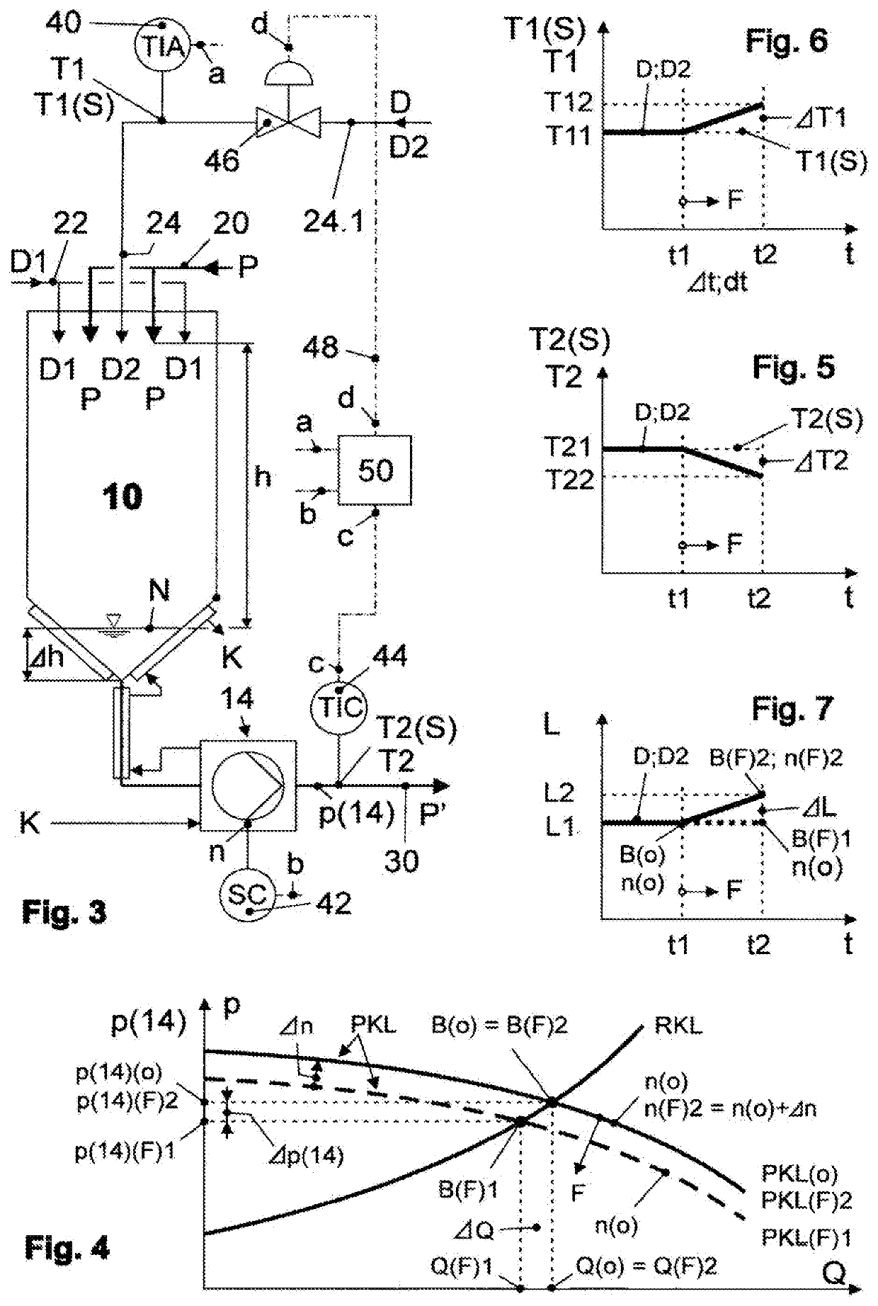
Controlling and / or treating heat-sensitive liquid food products ensures improved control of a filling level in an infuser container. Therefore, a constant dwell time of the product to be heated is reached in the event of product-fouling in the centrifugal pump. The pump is designed such that one part of a volume flow of the product, transported by an impeller wheel, regularly rinses the impeller wheel and the areas of a pump chamber that are directly adjacent to the impeller wheel. A reduction in the volume flow of the centrifugal pump is then counteracted by increasing the initial rotational speed if the reduction is simultaneously associated with a drop in temperature of the product. The increase of the initial rotational speed is carried according to the drop in temperature of the product and / or an increase in the temperature of the steam to constantly maintain at least the temperature of the product.

Description

TECHNICAL FIELD[0001]The invention relates to a method and a system for controlling and / or regulating the treatment of heat-sensitive liquid food products such as whey protein concentrate, baby food, liquid baby food concentrates, nutritious beverages or dairy milk, wherein steam directly heats the liquid food product to establish a germ-free state in an infuser container, wherein water is removed from the liquid food product by flash evaporation at a low pressure in an amount which corresponds to that of the previously supplied steam, wherein the liquid food product is delivered by means of a centrifugal pump between heating and flash evaporation, wherein the liquid food product undergoes cooling in at least one section of this flow path by each of the associated walls bordering this flow path starting upon entry into a base region of the infuser container and at most until entering the centrifugal pump. Moreover, the invention relates to a centrifugal pump for such a system.BACKGR...

Claims


Application Information

Patent Timeline
IPC IPC(8): A23C3/037A23L3/22
CPCA23V2002/00A23L3/22A23C3/037F04D29/588F04D29/426
Inventor SCHWENZOW, UWETACKE, LUDGERASSING, HUBERTBUSS, HELMUTLEIWERING, LUDGER
Owner GEA TDS
Learn More