Form dampening roller driving apparatus

Active Publication Date: 2005-02-01
MIYAKOSHI PRINTING MACHINERY
View PDF12 Cites 2 Cited by
  • Summary
  • Abstract
  • Description
  • Claims
  • Application Information

AI Technical Summary

Benefits of technology

Made to solve the problems mentioned above, the present invention is aimed to provide a form dampening roller driving apparatus whereby the slip ratio between the plate cylinder and the form dampening roller can be established, as d

Problems solved by technology

In this prior arrangement, however, continuous slipping contact between the form damping roller 6 and the plate cylinder 1 with the slip ratio held high results in the form dampening roller 6 rubbing the plate cylinder 1,

Method used


Image

  • Form dampening roller driving apparatus
  • Form dampening roller driving apparatus
  • Form dampening roller driving apparatus

Examples


Example

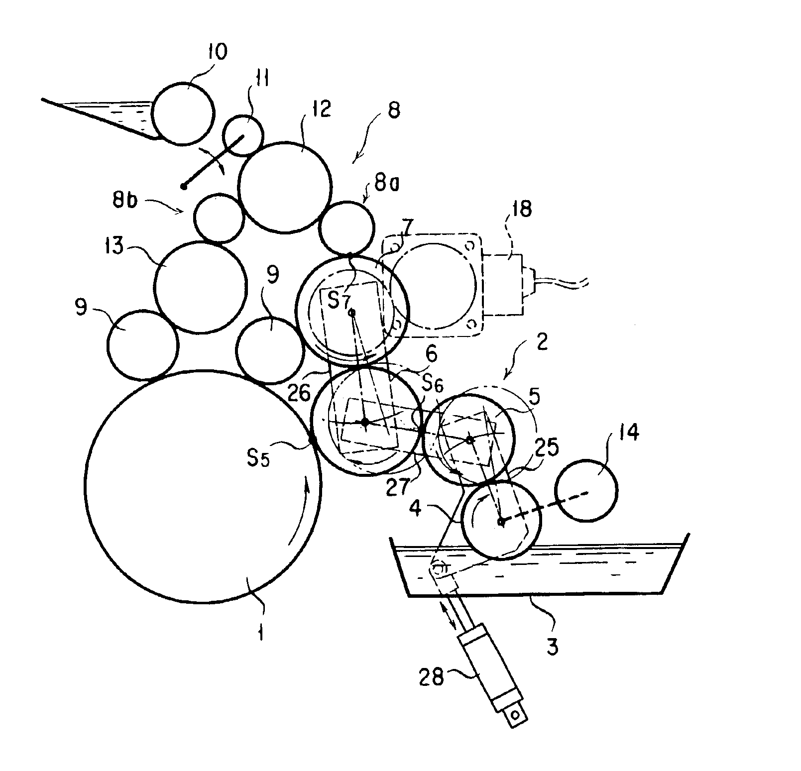
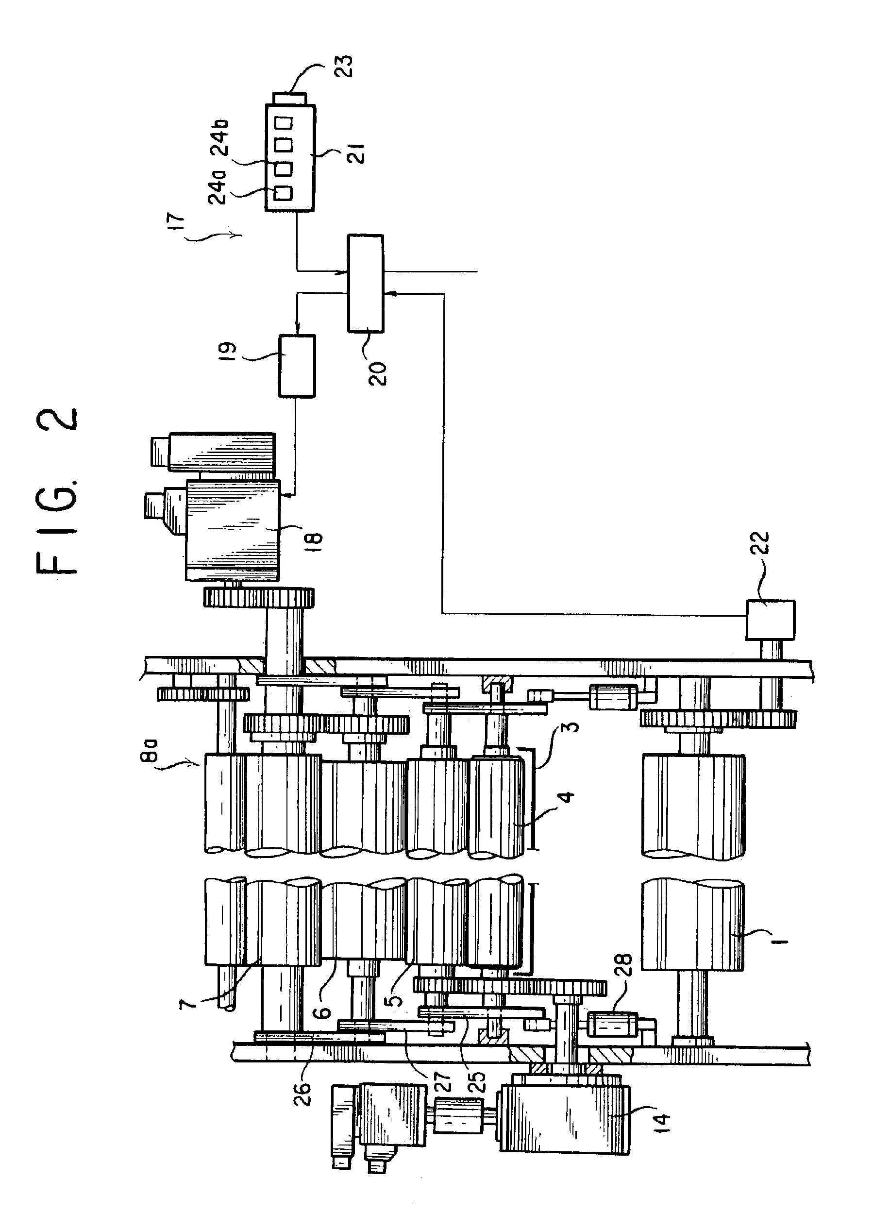
An explanation is hereafter given in respect of a certain form of implementation of the present invention with reference to FIGS. 1 and 2. It should be noted that the same reference characters as used in the preceding description of the prior arrangements as shown in FIGS. 3 to 5 are used to designate the same components or elements, of which repeated statements are therefore omitted here.

Referring first to FIG. 1, the water-fountain roller 4 is rotationally driven at a prescribed speed of rotation by the motor 14. The metering roller 5 in contact with the water fountain roller 4 is geared to the water fountain roller 4, and is designed to be rotated at a peripheral speed differing from that of the water fountain roller 4 and thus slipping relative to the water fountain roller 4. Here, the two rollers 4 and 5 are driven by the motor 14 to rotate at their respective peripheral speeds each held at a constant ratio to a peripheral speed of the plate cylinder 1.

The form dampening roller...


PUM


Abstract

A form dampening roller driving apparatus in which to obviate a hickey a slip is caused to occur between a form dampening roller and a plate cylinder in their mutual area of contact by rotationally driving the form dampening roller and the plate cylinder so they rotate having a difference in peripheral speed between them, and wherein the peripheral speed of the form dampening roller is made variable as desired to make the slip ratio between it and the plate cylinder in their mutual area of contact variable as desired. To this end, the form dampening roller is geared to a vibrator roller, and independent of a main motor for rotationally driving the plate cylinder there is provided a further motor for rotationally driving the form dampening roller independently of the plate cylinder at a rate of rotation that is made arbitrarily variable.

Description

BACKGROUND OF THE INVENTION1. Field of the InventionThe present invention relates to a form dampening roller driving apparatus that is applied to a form dampening device in an offset printing press.2. Description of the Prior ArtFIG. 3 shows a conventional roller arrangement for the offset printing press having a plate cylinder 1 rotationally driven by a main motor (not shown). A dampening device 2 is provided for supplying the peripheral surface of the plate cylinder 1 with water, thereby dampening a form (offset) plate wrapped around it. The dampening device 2 includes a water fountain roller 4 that is rotated while being in part dipped in a water tank 3, a metering roller (chrome roller) 5 that is rotated in contact with the water fountain roller 4 so that the mutually contacting surfaces of the rollers 4 and 5 move in a same direction, a form dampening roller 6 that is positioned between the metering roller 5 and the plate cylinder 1 for supplying water adhered on the metering r...

Claims


Application Information

Patent Timeline
IPC IPC(8): B41F7/00B41F7/26B41F33/10
CPCB41F7/26
Inventor NAKA, MASAHIROYAMAGATA, TOSHIYUKI
Owner MIYAKOSHI PRINTING MACHINERY
Why Eureka
Try Eureka