
Automatic recovery systems and methods for unmanned aircraft systems

a technology for aircraft systems and recovery systems, applied in vertical landing/take-off aircrafts, process and machine control, instruments, etc., can solve the problems of drones being often pushed harder, and the mean time between failures (mtbf) being reduced, and achieve the effect of high throttle setting

Inactive Publication Date: 2017-10-19
LATITUDE ENG
View PDF5 Cites 45 Cited by
  • Summary
  • Abstract
  • Description
  • Claims
  • Application Information

AI Technical Summary

Benefits of technology

The patent describes a system and method for automatically recovering an aircraft in case of a failure of the forward propulsion system. The system includes sensors to detect the failure and a controller to initiate a recovery sequence. The recovery sequence involves transitioning the aircraft to a vertical propulsion system for landing. The system can create a landing plan based on the aircraft's altitude and location at the time of failure detection. The technical effect of this invention is to enable safe recovery of an aircraft in the event of a failure of the forward propulsion system, reducing the risk of injury or damage to the aircraft.

Problems solved by technology

However, the small engines used in various Unmanned Aircraft Systems have demonstrated a lower reliability as compared to piloted aviation engines.
Also, because they don't transport people, drones are often pushed harder than piloted aircraft.
This greater demand on the aircraft systems can lead to a decreased mean time between failure (MTBF).
Loss of a UAS can be brought about by any of a number of different failure modes, such as engine failure, flight system or mechanical failure, communications link failures, and operator error.
However, engine failure is one of the more common, if not the primary cause of damage to or loss of small UAS and associated payloads.
Although human lives are not typically at stake when a UAS fails, there are costs associated with such failure.
These can include, for example, loss of the aircraft, loss of the payload, failure of the mission, and any collateral damage or losses.

Method used


Image

  • Automatic recovery systems and methods for unmanned aircraft systems
  • Automatic recovery systems and methods for unmanned aircraft systems
  • Automatic recovery systems and methods for unmanned aircraft systems

Examples


Embodiment Construction

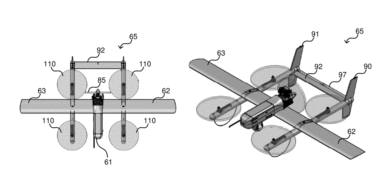
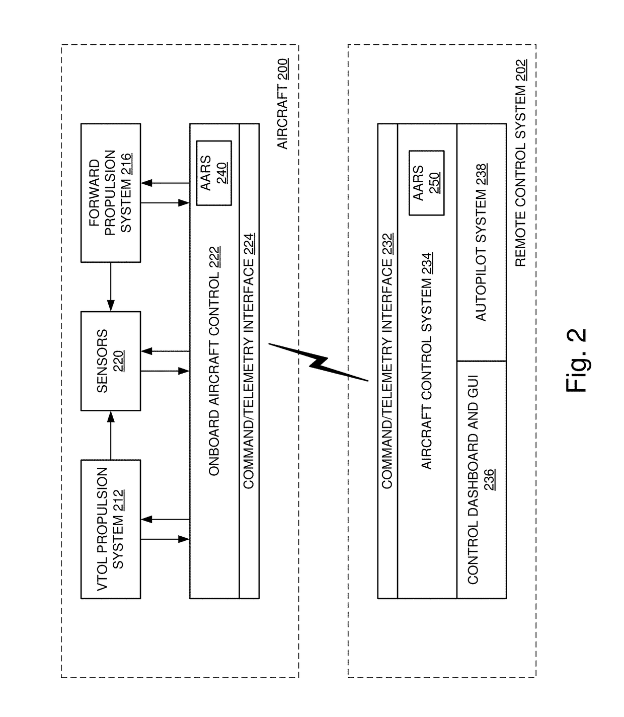
[0004]According to various embodiments of the disclosed technology systems and methods for automatic recovery to a landing configuration upon engine failure or other failure of unmanned aircraft are disclosed. In various embodiments, systems can be configured on board the aircraft, at the remote ground terminal, or both, to detect engine failure through a number of mechanisms and to initiate a recovery sequence in the event of a detected engine failure. In the case of a hybrid aircraft utilizing both a forward propulsion mechanism and a vertical takeoff and landing (VTOL) mechanism, the recovery sequence can include, for example, the creation and implementation of a recovery flight plan that includes transitioning the aircraft from a forward propulsion mode to a VTOL mode to enable VTOL landing. The system can be implemented to reconfigure the aircraft for a best glide (or other appropriate flight condition), create a landing plan within gliding range of the aircraft, initiate a lan...


PUM


Abstract

An aircraft, such as an unmanned aircraft, can include a forward propulsion system comprising one or more engines and one or more rotors coupled to a corresponding engine; a vertical propulsion system comprising one or more vertical propulsion engines and one or more corresponding rotors coupled thereto; a sensor package comprising one or more sensors to detect an operating parameter of the aircraft. It may further include an automatic recovery system that includes an input coupled to the sensor package; an output coupled to an aircraft controller; a processor to monitor one or more operating parameters of the aircraft, detect a failure of the forward propulsion system based on the operating parameters, and transition the aircraft to the vertical propulsion system for landing.

Description

TECHNICAL FIELD[0001]The disclosed technology relates generally to aircraft control systems, and more particularly, some embodiments relate to automatic recovery systems and methods for unmanned aircraft systems.DESCRIPTION OF THE RELATED ART[0002]Unmanned aircraft have become ubiquitous in today's society. Their importance and value has grown dramatically in recent years, leading to widespread adoption in commercial, military and consumer market sectors. Part of the reason for their popularity is their low cost and small form factor as compared to piloted aircraft. However, the small engines used in various Unmanned Aircraft Systems have demonstrated a lower reliability as compared to piloted aviation engines. Also, because they don't transport people, drones are often pushed harder than piloted aircraft. This greater demand on the aircraft systems can lead to a decreased mean time between failure (MTBF).[0003]Loss of a UAS can be brought about by any of a number of different failu...

Claims


Application Information

Patent Timeline
Patent Type & Authority Applications(United States)
IPC IPC(8): G05D1/06B64C29/00B64C39/02
CPCG05D1/0676B64C39/024B64C2201/141B64C2201/104B64C2201/108B64C29/0025G05D1/0055B64U30/10B64U2201/00B64U30/20B64U10/20B64U50/13B64U30/40B64U50/11
Inventor DOUGLAS, JASON MICHAEL K.ARMER, JUSTINMURPHY, CARLOS
Owner LATITUDE ENG
Learn More