Touch display panel, method for fabrication thereof and touch display device

Inactive Publication Date: 2017-10-19
BOE TECH GRP CO LTD +1
View PDF10 Cites 2 Cited by
  • Summary
  • Abstract
  • Description
  • Claims
  • Application Information

AI Technical Summary

Benefits of technology

The patent describes a touch display panel that has a layer of elastic material between two layers of glass. This layer of elastic material helps to prevent damage to the panel when it is pressed by an external force. This results in a longer lifespan for the touch display panel and reduces the likelihood of it getting damaged.

Problems solved by technology

However the anti-pressure ability of the touch display panel in the prior art is poor and easy to damage when pressed by an external force, therefore the lifetime of the touch display panel is reduced, i.e., the normal use of the touch screen display is affected.

Method used


Image

  • Touch display panel, method for fabrication thereof and touch display device
  • Touch display panel, method for fabrication thereof and touch display device
  • Touch display panel, method for fabrication thereof and touch display device

Examples


embodiment 1

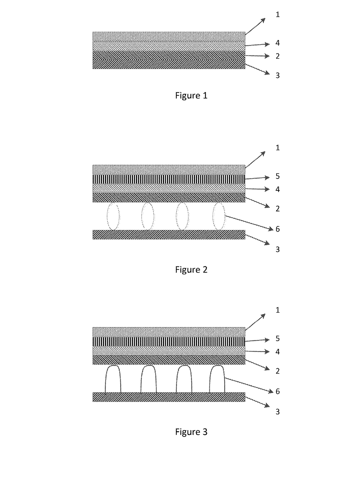
[0028]FIG. 1 shows a schematic structure diagram of a touch display panel according to embodiment 1. As shown in FIG. 1, the touch display panel according to embodiment 1 includes a touch substrate 1, a first display substrate 2, and a second display substrate 3, wherein the touch substrate 1, the first display substrate 2, and the second display substrate 3 are sequentially arranged, and an elastic buffer layer 4 is provided between the first display substrate 2 and the touch substrate 1.

[0029]Specifically, the elastic buffer layer 4 may be provided on the first display substrate 2 or under the touch substrate 1.

[0030]The touch display panel according to the embodiment can enhance greatly the anti-pressure ability of the touch display panel and increase the lifetime of the touch display panel by providing the elastic buffer layer 4 between the touch substrate 1 and the first display substrate 2 such that when the touch display panel is pressed by the external force, the elastic buf...

embodiment 2

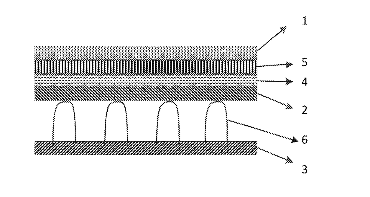
[0031]FIG. 2 shows a schematic structure diagram of a touch display panel according to embodiment 2. As shown in FIG. 2, the touch display panel according to embodiment 2 includes a touch substrate 1, a first display substrate 2, and a second display substrate 3, wherein the touch substrate 1, the first display substrate 2, and the second display substrate 3 are sequentially arranged, and an elastic buffer layer 4 is provided between the first display substrate 2 and the touch substrate 1. The elastic buffer layer 4 is provided on the first display substrate 2. An optically clear adhesive (OCA) layer 5 or an optically clear resin (OCR) layer 5 is provided between the touch substrate 1 and the elastic buffer layer 4. The elastic buffer layer 4 is laminated with the touch substrate 1 by the optically clear adhesive layer or the optically clear resin layer.

[0032]In the embodiment, spacers 6 are provided between the first display substrate 2 and the second display substrate 3, and the m...

embodiment 3

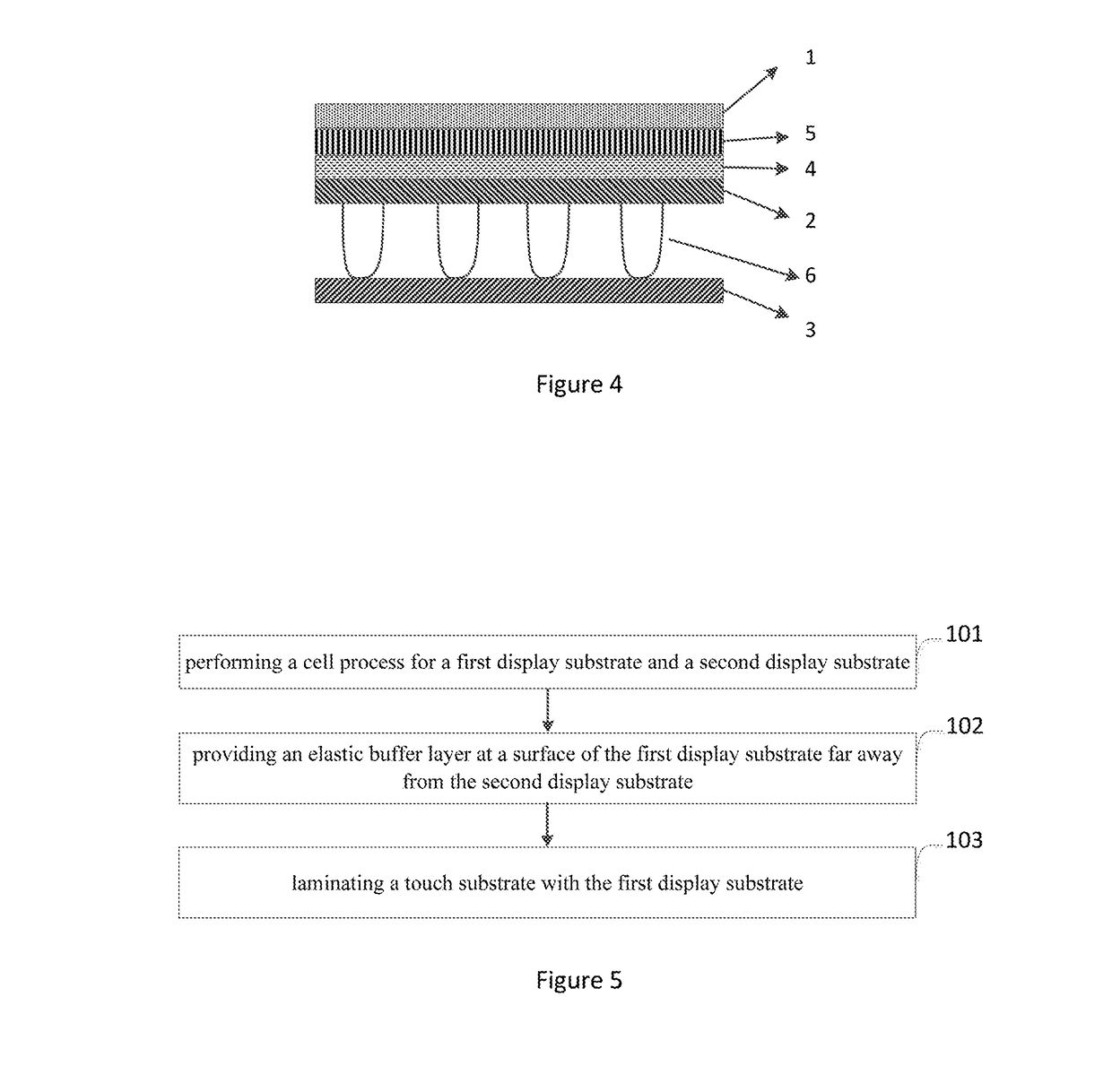
[0036]FIG. 3 shows a schematic structure diagram of a touch display panel according to embodiment 3. The touch display panel according to embodiment 3 is same as the touch display panel according to embodiment 2 in addition to the spacers. The description of the same parts is omitted here for brevity. As shown in FIG. 3, the end faces that the spacers 6 contact the first display substrate 2 are arcing structures.


PUM


Abstract

The embodiments of the disclosure disclose a touch display panel including a touch substrate, a first display substrate, and a second display substrate, wherein the touch substrate, the first display substrate, and the second display substrate are sequentially arranged, and an elastic buffer layer is provided between the first display substrate and the touch substrate. When the touch display panel according to embodiments of the disclosure is pressed by the external force, the elastic buffer layer is able to release the external force in a way of shape change such that the impact of the external forces on the touch display panel can be avoided or mitigated and the anti-pressure ability of the touch display panel can be enhanced.

Description

CROSS REFERENCE TO RELATED APPLICATIONS[0001]This application is a National Stage Entry of PCT / CN2016 / 074010 filed Feb. 18, 2016, which claims the benefit and priority of Chinese Patent Application No. 201510124542.4, filed on Mar. 19, 2015, the disclosures of which are incorporated by reference herein in their entirety as a part of the present application.BACKGROUND[0002]The embodiments of the disclosure relate to touch display panels, methods for fabrication thereof, and touch display devices.[0003]Touch screen display can let users use their fingers to touch an icon or text on the touch screen display in order to implement host operations, such that the keyboard and mouse operations can be get rid of and man-machine interaction become simpler. The touch screen display has become a mainstream display device currently.[0004]However the anti-pressure ability of the touch display panel in the prior art is poor and easy to damage when pressed by an external force, therefore the lifeti...

Claims


Application Information

Patent Timeline
IPC IPC(8): G06F3/041
CPCG06F2203/04103G06F3/041G02F1/13338G02F2201/503G06F3/0412
Inventor CHEN, CHANGDIYANG, TAOLUO, YIYONG
Owner BOE TECH GRP CO LTD
Why Eureka
Try Eureka