

Liquid crystal display panel comprising conductive structure and liquid crystal display device
- Summary
- Abstract
- Description
- Claims
- Application Information
AI Technical Summary
Benefits of technology
Problems solved by technology
Method used
Image

Examples
Embodiment Construction
[0013]In order to make objects, technical details and advantages of the embodiments of the invention apparent, hereinafter, technical solutions in embodiments of the present invention will be clearly and fully described in combination with the accompanied drawings in the embodiments of the present invention. Apparently, the embodiments to be described are merely a part but not all of embodiments of the present invention. Every other embodiment as would be obvious to those ordinarily skilled in the art on the basis of described embodiments in the present invention without creative work, comes within the protection scope of the present invention.
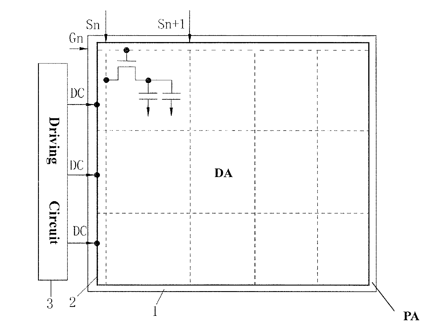
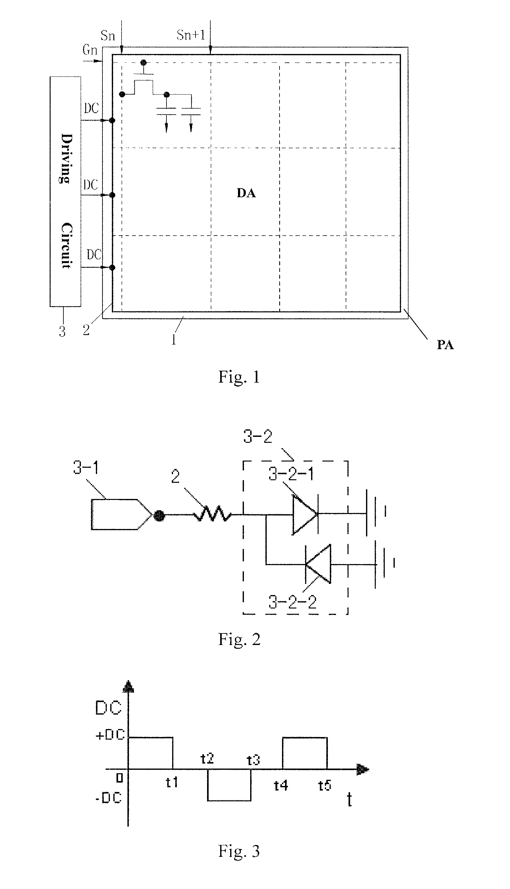
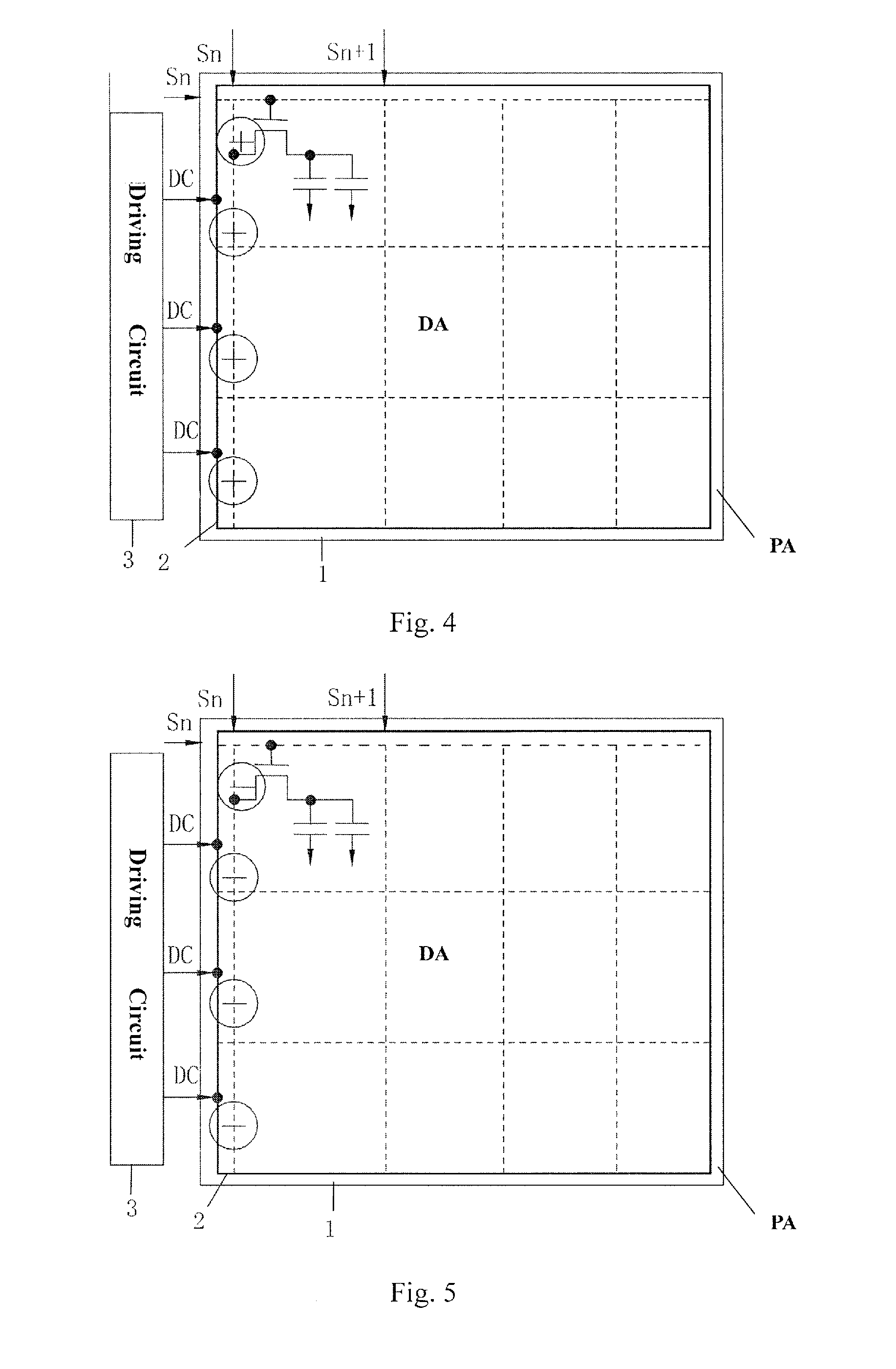
[0014]Compared to a liquid crystal display panel of vertical electric field mode, image sticking more likely occurs in a liquid crystal display panel of horizontal electric field mode. For example, in a FFS-type TFT-LCD of horizontal electric field mode, the horizontal electric field is generated by a pixel electrode and a common electrode tha...
PUM
 Abstract
Description
Claims
Application Information