
Touch-sensing panel and touch-sensing liquid crystal display panel using the same

a touch sensor and liquid crystal display panel technology, applied in the direction of instruments, computing, electric digital data processing, etc., can solve the problems of limited thickness and weight achieve the reduction of the manufacturing cost the thickness of the touch sensor liquid crystal display panel can be accordingly reduced, and the effect of reducing the manufacturing cos

Inactive Publication Date: 2014-01-16
HANNSTOUCH SOLUTION
View PDF1 Cites 11 Cited by
  • Summary
  • Abstract
  • Description
  • Claims
  • Application Information

AI Technical Summary

Benefits of technology

The present invention provides a touch-sensing panel and a touch-sensing liquid crystal display panel that can reduce thickness and weight, and decrease manufacturing costs by eliminating the need for a transparent substrate and reducing the amount of patterned sensing electrode layers needed. This is achieved by directly forming a patterned sensing electrode layer on the surface of the second polarization plate, resulting in a thinner and lighter touch-sensing liquid crystal display panel.

Problems solved by technology

Thus, the thickness and the weight of the touch-sensing liquid crystal display panel are limited by the thicknesses and the weights of the liquid crystal display panel and the touch-sensing panel themselves.

Method used


Image

  • Touch-sensing panel and touch-sensing liquid crystal display panel using the same
  • Touch-sensing panel and touch-sensing liquid crystal display panel using the same
  • Touch-sensing panel and touch-sensing liquid crystal display panel using the same

Examples


Embodiment Construction

[0020]To provide a better understanding of the present invention, exemplary embodiments will be detailed as follows. The exemplary embodiments of the present invention are illustrated in the accompanying drawings with numbered elements to elaborate the contents and effects to be achieved.

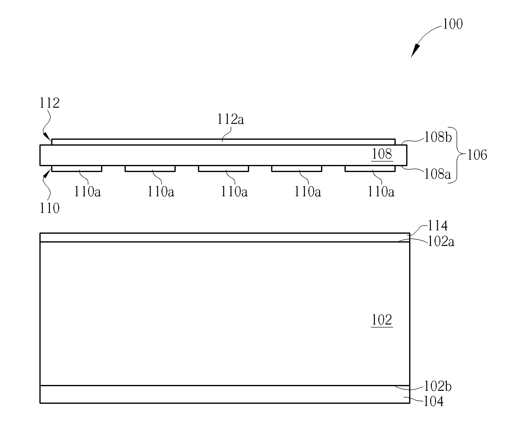
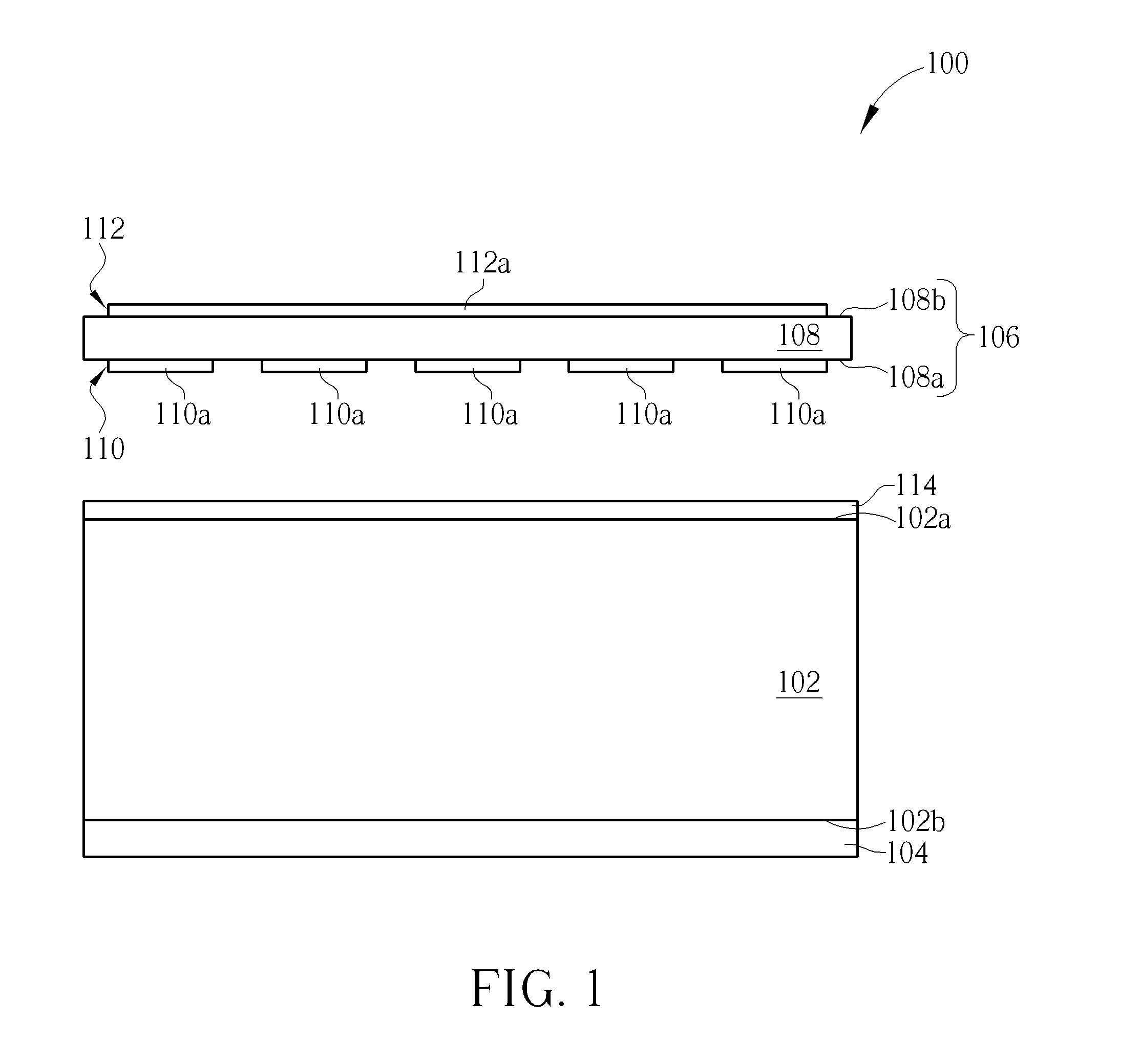
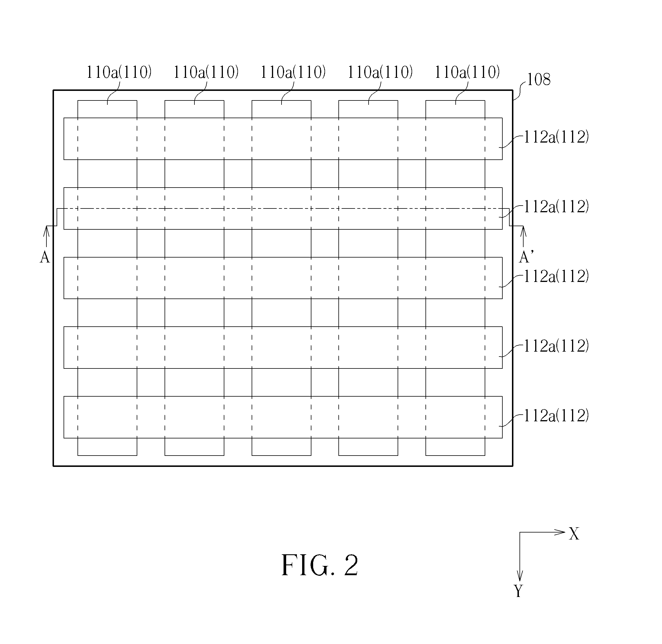
[0021]Please refer to FIG. 1 and FIG. 2. FIG. 1 is a schematic diagram illustrating an exploded cross-sectional view of a touch-sensing liquid crystal display panel according to a first embodiment of the present invention, and FIG. 2 is a schematic diagram illustrating a top view of a touch-sensing panel according to the first embodiment of the present invention, wherein FIG. 1 is the exploded cross-sectional view of FIG. 2 taken along a cross-sectional line A-A′. As shown in FIG. 1, the touch-sensing liquid crystal display panel 100 includes a liquid crystal panel 102, a first polarization plate 104, and a touch-sensing panel 106. The liquid crystal panel 102 has a display surface 102a and a back s...


PUM

PropertyMeasurementUnit
transparentaaaaaaaaaa
thicknessaaaaaaaaaa
weightaaaaaaaaaa

Abstract

The present invention provides a touch-sensing panel including a polarization plate and a patterned sensing electrode layer. The polarization plate has a first surface and a second surface, and the first surface and the second surface are disposed opposite to each other. The first patterned sensing electrode layer is disposed on the first surface, and the first patterned sensing electrode layer is directly attached on the first surface of the polarization plate.

Description

BACKGROUND OF THE INVENTION[0001]1. Field of the Invention[0002]The present invention relates to a touch-sensing panel and a touch-sensing liquid crystal display panel using the same, and more particularly, to a touch-sensing panel having a patterned sensing electrode layer directly formed on a polarization plate and a touch-sensing liquid crystal display panel using the same.[0003]2. Description of the Prior Art[0004]The touch-sensing panel has been widely used in the input interfaces of the instruments for its properties such as the great interaction between machines and humans. In recent years, more consumer electronics, such as mobile phones, GPS navigator systems, tablet computers, personal digital assistances (PDA), and laptop computers are employed with touch display panels. In general, the touch-sensing panel is combined with the liquid crystal display panel to form a touch-sensing liquid crystal display panel. However, the liquid crystal display panel and the touch-sensing ...

Claims


Application Information

Patent Timeline
Patent Type & Authority Applications(United States)
IPC IPC(8): G06F3/041G02F1/1333
CPCG06F3/0412G02F1/13338G02F1/133528G06F3/0445G06F3/0446G06F2203/04103B32B2457/208G02F1/13439G06F3/047
Inventor TUNG, KUO-HSIUNGHSU, PIN-YUSU, CHUAN-HUI
Owner HANNSTOUCH SOLUTION
Learn More