Light Trolley System

a trolley system and light technology, applied in the field of light trolley systems, can solve the problems of not always meeting the needs of lighting, achieve the effects of maximizing the coverage area, quality of light, and useable growing area, and increasing labor efficiency in the growing area

Active Publication Date: 2017-10-26
MJNN LLC
View PDF1 Cites 19 Cited by
  • Summary
  • Abstract
  • Description
  • Claims
  • Application Information

AI Technical Summary

Benefits of technology

[0005]The present invention is a light trolley system for vertical-plane growing that maximizes the coverage area, quality of light, and useable growing area. The light trolley system comprises a support structure and first C rail secured to the support structure. The first C rail has a first end and a second end. A first brace is mounted to the first C rail and a first light trolley secured to the first brace. The first light trolley has at least one bar light mounted within a light manifold. The first brace supports and stabilizes the first light trolley. The combined first brace and first light trolley is moveable along the first C rail between the first end and the second end of the first C rail allowing the first light trolley to be moved to various locations increasing labor efficiency in the growing area.
[0006]In addition, the present invention includes a method for vertical-plane growing that maximizes the coverage area, quality of light, and useable growing area. The method system comprises providing a support structure, securing a pair of spaced, parallel C rails to the support structure with each of the C rails having a first end and a second end, mounting a first brace to is the C rails, securing a first light trolley to the first brace with the first light trolley having at least one bar light mounted within a light manifold, supporting and stabilizing the first light trolley with the first brace, moving the combined first brace and first light trolley along the C rails, and al

Problems solved by technology

High intensity indoor growing environments have unique lighting n

Method used


Image

  • Light Trolley System
  • Light Trolley System
  • Light Trolley System

Examples


Embodiment Construction

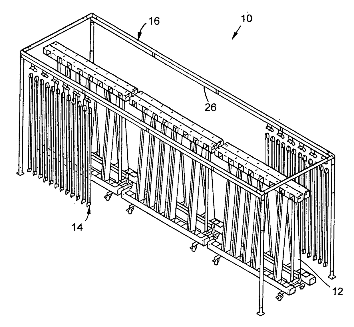
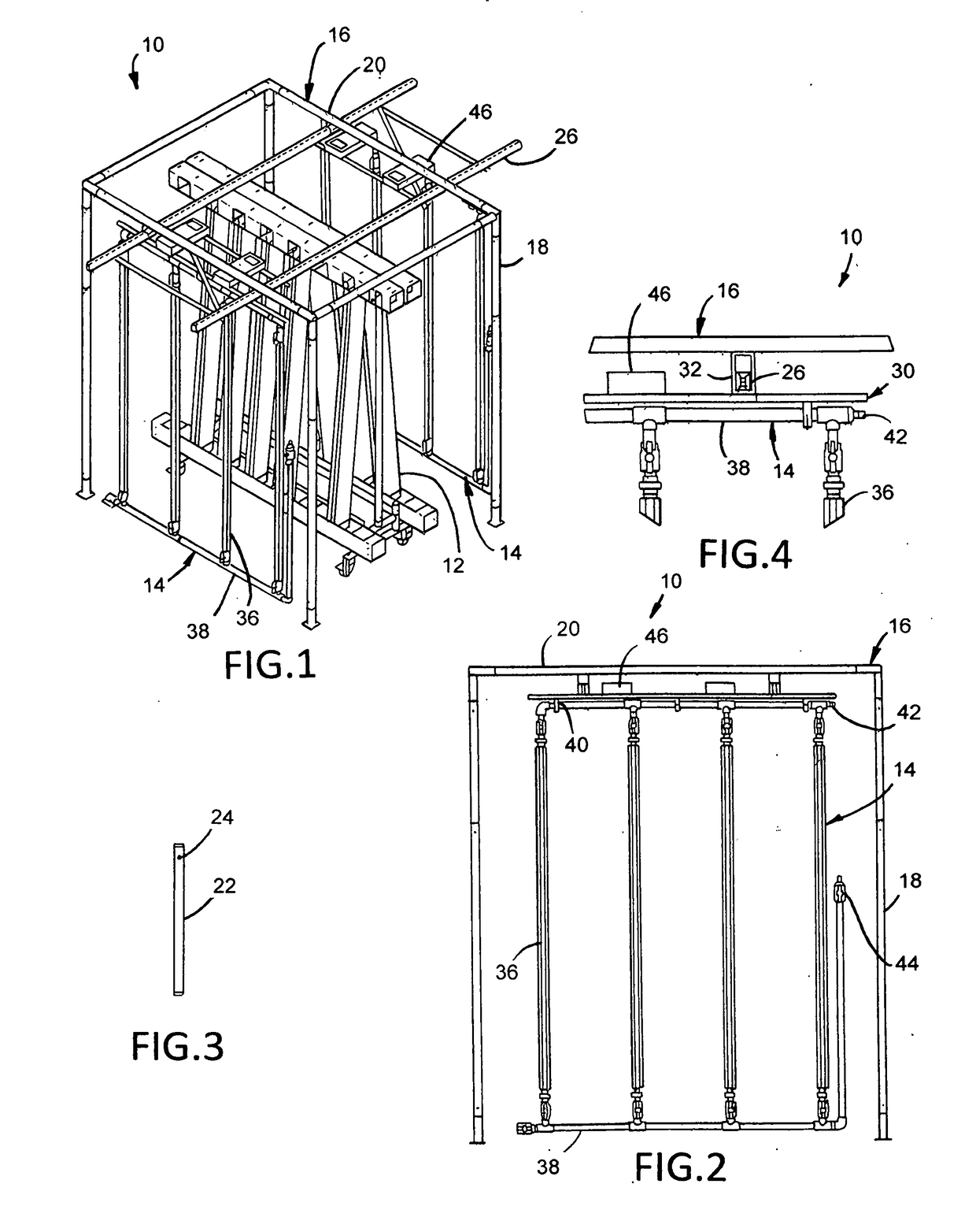
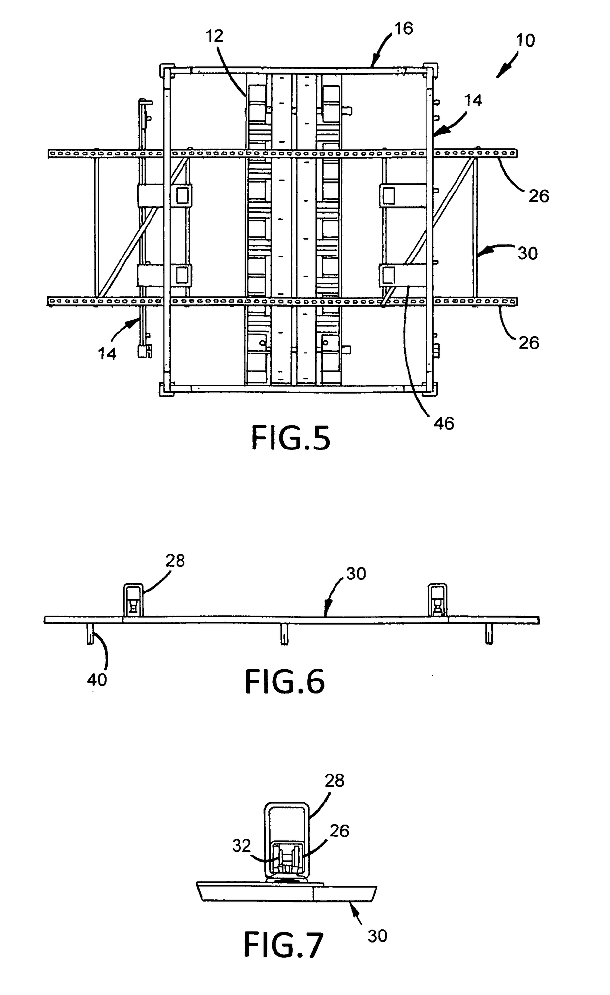
[0022]As illustrated in FIGS. 1-14, the present invention is a light trolley system, indicated generally at 10, for vertical-plane growing in growing towers 12 and the like that maximizes the coverage and quality of the light and enables the space to be useable. The purpose of the light trolley system 10 of the present invention is to allow hanging of bar-type horticultural lights or light trolleys 14 allowing the lights to be water cooled and allowing the lights to be moved out of the way using the light trolley system 10 so that labor can be more efficiently used in the growing area.

[0023]The light trolley system 10 of the present invention includes a modular support structure 16 having a plurality of vertical support members 18 and a plurality of horizontal support members 20. Preferably, the modular support structure 16 includes four spaced vertical support members 18 with a horizontal support members 20 connected to the end and extending between adjacent vertical support member...


PUM


Abstract

A light trolley system for vertical-plane growing that maximizes the coverage area, quality of light, and useable growing area is provided. The light trolley system comprises a support structure and a first C rail secured to the support structure. The first C rail has a first end and a second end. A first brace is mounted to the first C rail and a first light trolley secured to the first brace. The first light trolley has at least one bar light mounted within a light manifold. The first brace supports and stabilizes the first light trolley. The combined first brace and first light trolley is moveable along the first C rail between the first end and the second end of the first C rail allowing the first light trolley to be moved to various locations increasing labor efficiency in the growing area.

Description

[0001]The present application claims benefit of priority from pending U.S. provisional patent application Ser. No. 62 / 324,912, filed Apr. 20, 2016, entitled “Light Fixture System”.BACKGROUND OF THE INVENTION1. Field of the Invention[0002]This invention relates generally to a light trolley system and, more particularly, the invention relates to a light trolley system for vertical-plane growing that maximizes the coverage and quality of the light and enables the space to be useable.2. Description of the Prior Art[0003]High intensity indoor growing environments have unique lighting needs that are not always met by traditional lighting form-factors. Developing these form factors requires not only new lighting designs, but new designs for mounting lighting and utilizing these lights in a way that maximizes light use efficiencies within the farm.[0004]Vertical-plane growing is no exception, and requires light fixture systems that both hang the lights in a way that maximizes the coverage a...

Claims


Application Information

Patent Timeline
IPC IPC(8): A01G9/20A01G1/00F21V29/58F21S4/28F21V21/14A01G7/04
CPCA01G9/20A01G7/045F21V21/14F21V29/58F21S4/28A01G1/001A01G9/249A01G22/00Y02A40/25
Inventor SMITH, DAMON HENRYSTOREY, NATHANIEL R.WOLLERT, TAYLOR BROOKE
Owner MJNN LLC
Why Eureka
Try Eureka