

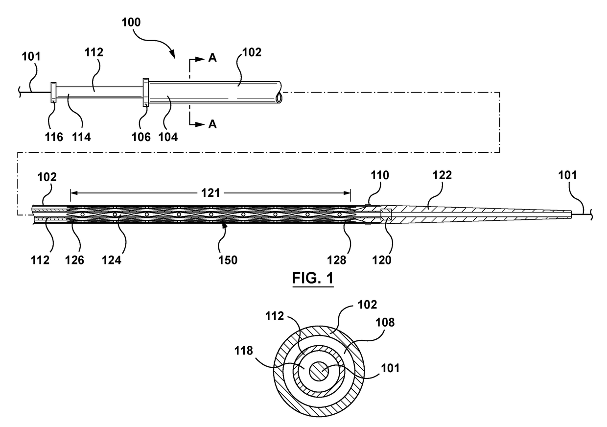
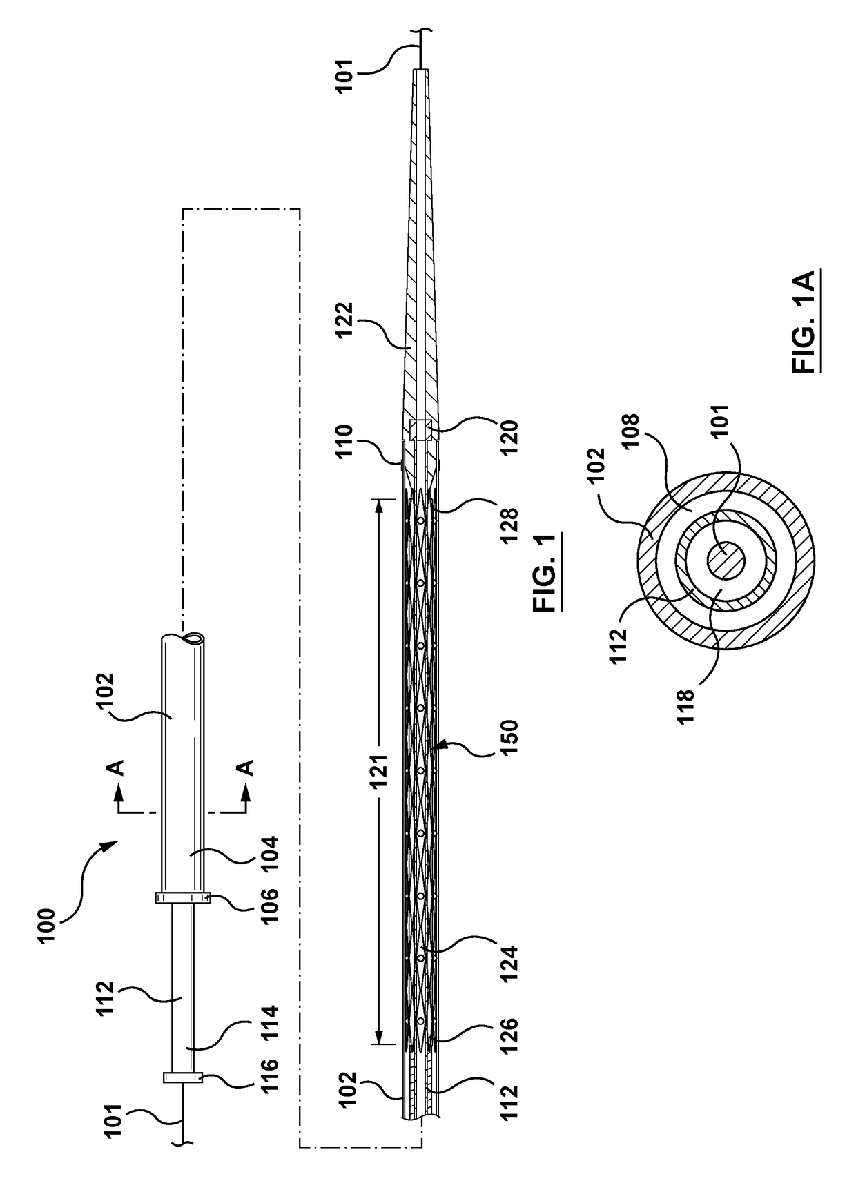
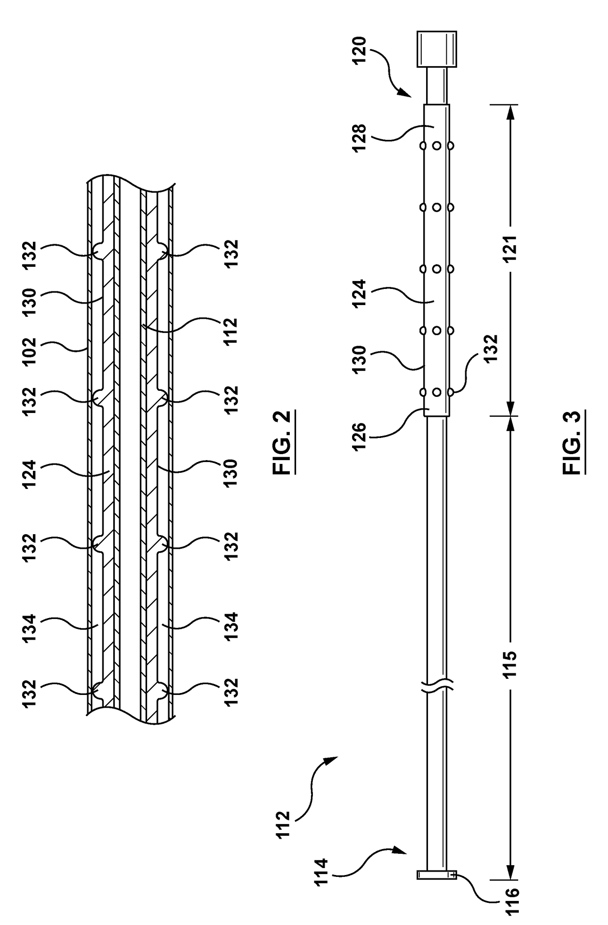
Stent-graft delivery system having an inner shaft component with a loading pad or covering on a distal segment thereof for stent retention
a stent and inner shaft technology, applied in the field of implantable prostheses, can solve the problems of internal bleeding and potentially life-threatening conditions, lack of axial strength of self-expanding stent-grafts, and weak blood vessel walls
- Summary
- Abstract
- Description
- Claims
- Application Information
AI Technical Summary
Benefits of technology
Problems solved by technology
Method used
Image

Examples
Embodiment Construction
[0020]Specific embodiments are now described with reference to the figures, wherein like reference numbers indicate identical or functionally similar elements. Unless otherwise indicated, for the delivery system the terms “distal” and “proximal” are used in the following description with respect to a position or direction relative to the treating clinician. “Distal” and “distally” are positions distant from or in a direction away from the clinician, and “proximal” and “proximally” are positions near or in a direction toward the clinician. In addition, the term “self-expanding” is used in the following description with reference to one or more stents or scaffolds of the prostheses hereof and is intended to convey that the structures are shaped or formed from a material that can be provided with a mechanical memory to return the structure from a compressed or constricted delivery configuration to an expanded deployed configuration. Non-exhaustive exemplary self-expanding materials inc...
PUM
 Abstract
Description
Claims
Application Information