
Auxiliary seat storage structure

a technology for auxiliary seats and storage structures, which is applied in the field of auxiliary seats, can solve the problems of limiting usability, inconvenience for users, and lack of storage space for auxiliary seats, so as to improve convenience and usability for users, improve storage capacity, and improve convenience and usability

Active Publication Date: 2017-10-26
HYUNDAI MOTOR CO LTD +2
View PDF0 Cites 4 Cited by
  • Summary
  • Abstract
  • Description
  • Claims
  • Application Information

AI Technical Summary

Benefits of technology

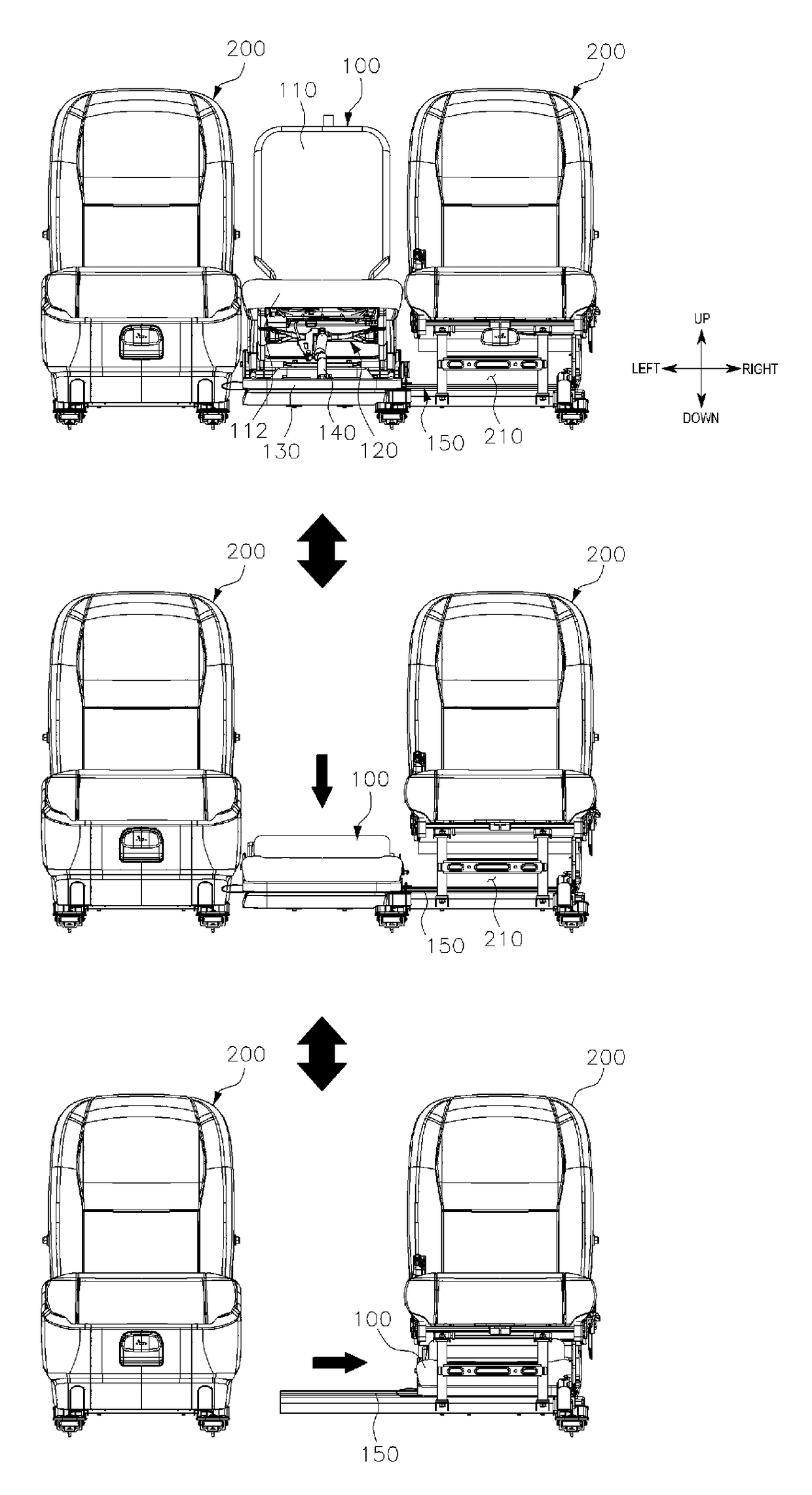
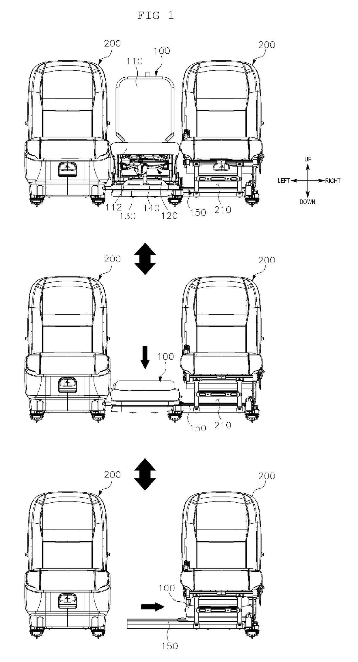
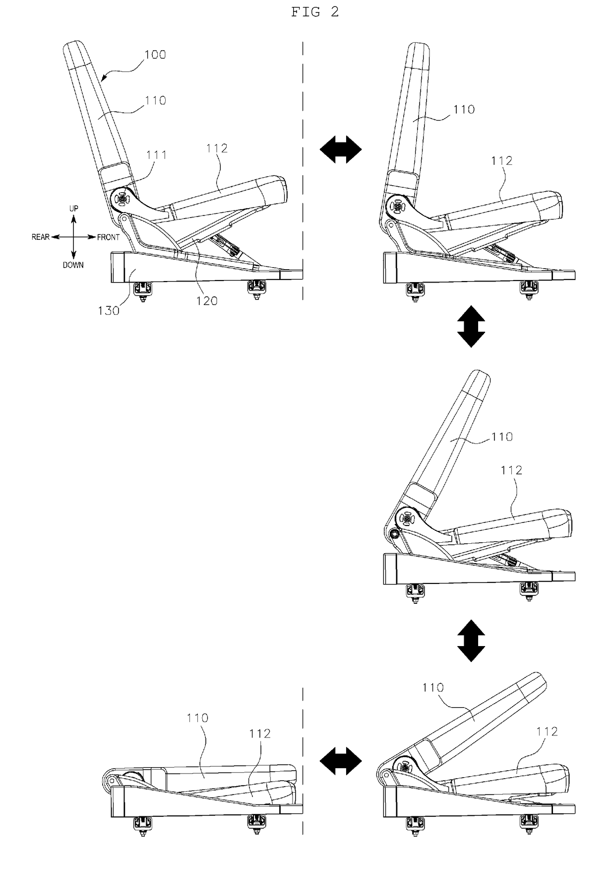
The present patent provides an auxiliary seat storage structure that maximizes storage space and minimizes steps for operation. The auxiliary seat can slide into a lower cavity of an exterior seat when folded and divided. The structure improves storage capacity and convenience, as the seat cushion does not protrude forward when the auxiliary seat is folded and slidable locking is automatically released. Additionally, the patent improves the marketability of vehicles by enabling a two-person mode or a three-person mode as per user needs, with the auxiliary seat optionally adjusted with the exterior seats.

Problems solved by technology

Accordingly, the occupant is inconvenienced due to a narrow passageway cavity when the occupant enters or exits the seat disposed in the third row.
However, this structure does not provide for the auxiliary seat to be drawn out or stored when the occupant is seated on the exterior seat or a child seat is installed on the exterior seat.
The double folding structure in the related art stores the auxiliary seat in the exterior seat requires the double folding structure to be operated through four steps of folding a seat back of the auxiliary seat, opening the seat cushion of the exterior seat, side-folding the folded auxiliary seat at 180 degrees and storing the folded auxiliary seat in the exterior seat and closing the seat cushion of the exterior seat, which limits the usability.
Accordingly, the auxiliary seat causes interference with a seat disposed in a first row or the auxiliary seat is difficult to store.
In addition, catching portions may be formed on the lower rail to capture both ends of the locker and when the locker is captured by the catching portion, the sliding movement of the auxiliary seat may be restricted.

Method used


Image

  • Auxiliary seat storage structure
  • Auxiliary seat storage structure
  • Auxiliary seat storage structure

Examples


Embodiment Construction

[0029]The present invention will be described more fully hereinafter with reference to the accompanying drawings, in which exemplary embodiments of the invention are shown. While the invention will be described in conjunction with exemplary embodiments, it will be understood that present description is not intended to limit the invention to those exemplary embodiments. On the contrary, the invention is intended to cover not only the exemplary embodiments, but also various alternatives, modifications, equivalents and other embodiments, which may be included within the spirit and scope of the invention as defined by the appended claims.

[0030]A part irrelevant to the description will be omitted to clearly describe the present disclosure, and the same or similar constituent elements will be designated by the same reference numerals throughout the specification. Terms or words used in the specification and the claims should not be interpreted as being limited to a general or dictionary m...


PUM


Abstract

A structure of an auxiliary seat disposed in a second row in a vehicle is provided. The auxiliary seat storage structure includes an auxiliary seat that is disposed between a pair of exterior seats and has a seat back rotatably coupled to a seat cushion by a recliner and a rail that is installed in a vehicle width direction. The auxiliary seat is configured to slide into an internal cavity at a lower end of the exterior seat. The auxiliary seat slides along the rail when the auxiliary seat is folded and simultaneously adjusted downward and is stored in a lower cavity of the exterior seat. A passageway cavity is maximized, the number of operating steps are minimized and the auxiliary seat are stored regardless of whether an occupant is seated on the exterior seat.

Description

CROSS-REFERENCE TO RELATED APPLICATIONS[0001]This application claims priority under 35 U.S.C. §119 to Korean Patent Application No. 10-2016-0048521, filed on Apr. 21, 2016 with the Korean Intellectual Property Office, the disclosure of which is incorporated herein by reference in its entirety.BACKGROUND1. Field of the Invention[0002]The present invention relates to an auxiliary seat disposed in a second row of a vehicle, and more particularly, to an auxiliary seat storage structure that maximizes convenience when a passenger s enters and exits the vehicle since the auxiliary seat slides along a rail and then is stored in a lower cavity of an exterior seat.2. Description of the Related Art[0003]Generally, a seat for a vehicle is installed in the vehicle to support an occupant's body and reduce a degree of fatigue caused when the vehicle travels. Further, the seat for a vehicle provides comfortable ride and includes a seat cushion which supports an occupant's hip, a seat back which is...

Claims


Application Information

Patent Timeline
IPC IPC(8): B60N2/30B60N2/08B60N2/06B60N2/01
CPCB60N2/309B60N2/062B60N2/3011B60N2/065B60N2/3061B60N2/0806B60N2/01B60N2/3081B60N2/3065B60N2/30B60N2/3009B60N2/3059B60N2/3072
Inventor PARK, IL-HONGLEE, BYUNG-JAEPARK, HYUN-KYUMOON, SOO-HYUNHEO, JUN-YEOLKIM, SANG-HOJUNG, DAE-IGJIN, KEON-SOOKIM, HYUKKIM, DO-KYUNLEE, SANG-DONGKIM, KYU-JINKIM, TAE-HYUNG
Owner HYUNDAI MOTOR CO LTD
Learn More