

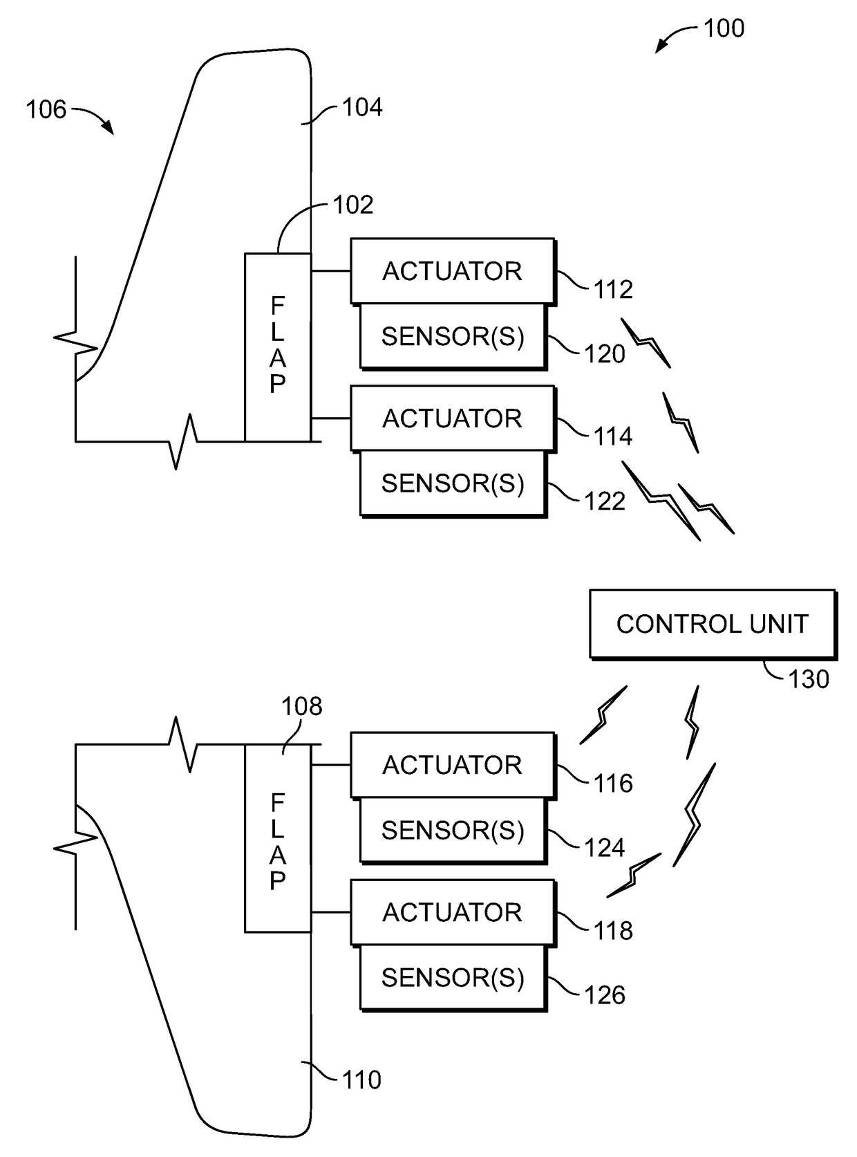
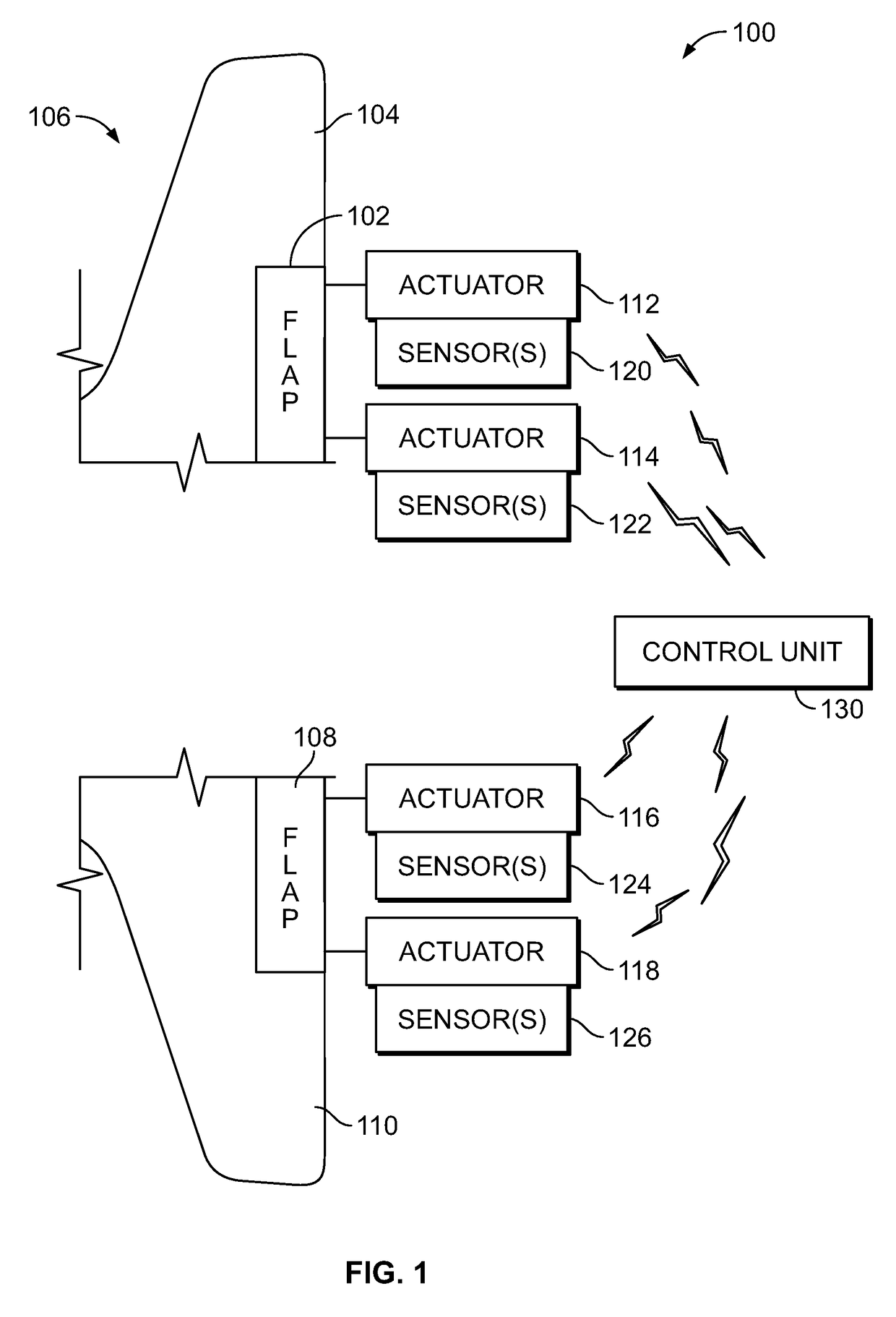
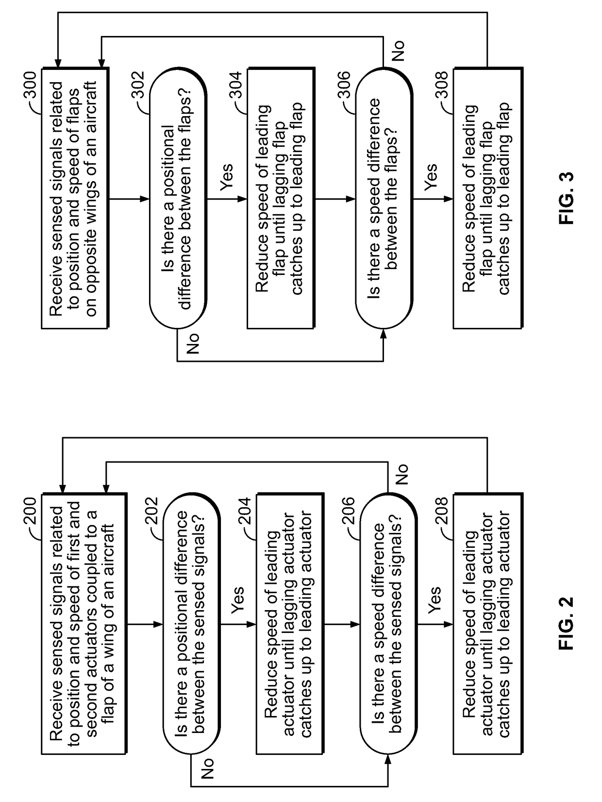
System and method for controlling aircraft wing flap motion
a technology for controlling the motion of the wing flap and the wing, which is applied in the direction of power amplification, movable aircraft element position indicators, aircraft power plants, etc., can solve the problems of flaps being susceptible flaps may be prone to skewing or twisting under sufficient airload, etc., and achieve the effect of increasing the speed of the lagging and decreasing the speed of the leading
- Summary
- Abstract
- Description
- Claims
- Application Information
AI Technical Summary
Benefits of technology
Problems solved by technology
Method used
Image

Examples
Embodiment Construction
[0023]The foregoing summary, as well as the following detailed description of certain embodiments will be better understood when read in conjunction with the appended drawings. As used herein, an element or step recited in the singular and preceded by the word “a” or “an” should be understood as not necessarily excluding the plural of the elements or steps. Further, references to “one embodiment” are not intended to be interpreted as excluding the existence of additional embodiments that also incorporate the recited features. Moreover, unless explicitly stated to the contrary, embodiments “comprising” or “having” an element or a plurality of elements having a particular condition may include additional elements not having that condition.
[0024]Embodiments of the present disclosure are applicable to high lift actuation systems that use distributed flap actuation. Embodiments of the present disclosure provide systems and methods that reduce flap skew by sensing a position and / or speed ...
PUM
 Abstract
Description
Claims
Application Information