De-stacking device for de-stacking layers of transport pallets with or without intermediary layers

a transport pallet and de-stacking technology, which is applied in the direction of de-stacking articles, conveyors, stacking articles, etc., can solve the problems of not being universally useful, stacking devices cannot be used for de-stacking transport pallets, and transport pallet de-stacking without a separation layer between stacking layers is not possible, so as to achieve low mechanical complexity

Active Publication Date: 2017-10-26
MARTINMECHANIC FRIEDRICH MARTIN
View PDF3 Cites 3 Cited by
  • Summary
  • Abstract
  • Description
  • Claims
  • Application Information

AI Technical Summary

Benefits of technology

[0006]Improving upon the prior art it is an object of the invention to propose a de-stacking device for de-stacking layers of stacked transport pallets wherein the de-stacking device is universally usable and configured to de-stack stacking layers with and without an intermediary layer and configured to transfer the transport goods of the stacking layers from the placement and separation table to an extraction conveyor. Furthermore removing the spacers shall be achievable with low mechanical complexity.

Problems solved by technology

It is a perceived disadvantage of these stacking devices that they are not universally useable.
In particular the stacking devices can only be used for de-stacking transport pallets where a separation layer or a spacer is provided between the stacking layers.
Thus, de-stacking transport pallets without a separation layer between the stacking layers is not possible.

Method used


Image

  • De-stacking device for de-stacking layers of transport pallets with or without intermediary layers
  • De-stacking device for de-stacking layers of transport pallets with or without intermediary layers
  • De-stacking device for de-stacking layers of transport pallets with or without intermediary layers

Examples


Embodiment Construction

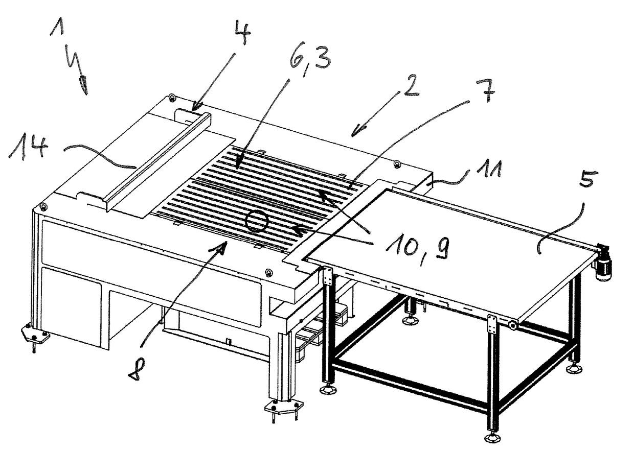
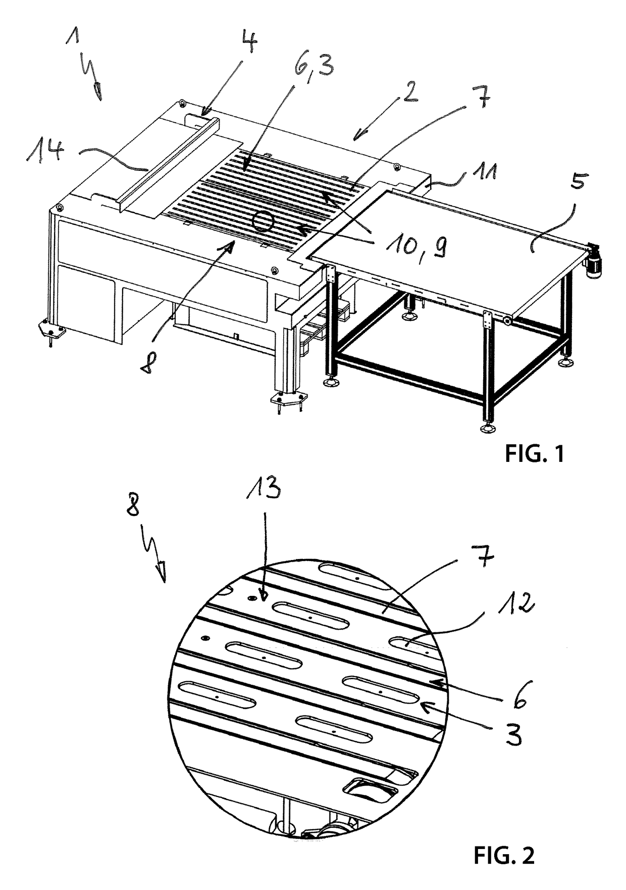
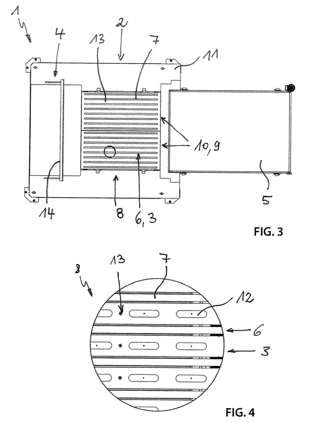
[0025]FIG. 1 illustrates a de-stacking device 1 for layered de-stacking of transport pallets not illustrated in FIGS. 1-3, wherein the transport pallets include a multi-layer stack of stacking layers that are arranged on top of one another under which a respective bending stiff spacer is optionally arranged. The non-illustrated stacking layers are formed by stable standing stackable transport goods that are arranged adjacent to each other. The de-stacking device 1 includes a placement and separation table 2 for a respective stacking layer removed from a top of a stack of the transport pallets with or without the spacer which stacking layer is transferred onto the placement and separation table by a transfer device that is not illustrated in FIGS. 1-3 for the stacking layer with or without the spacer of the stack of the transport pallet. The transfer device includes a pivot arm robot with a gripper system which moves the stacking layer with or without the spacer in three dimensions. ...


PUM


Abstract

A de-stacking device for layer de-stacking stacking layers from standard transport pallets which include a multi-layer stack of stacking layers arranged on top of each other, wherein an optional bending stiff spacer is arranged under each of the stacking layers, wherein the stacking layers are formed by a plurality of stable standing transport goods that are stackable and arranged adjacent to each other, the de-stacking device including a placement and separation table for a respective stacking layer that is removed from the stack of the transport pallet and includes or does not include the optional spacer; a transfer device for transferring the respective stacking layer that includes or does not include the optional spacer from the stack of the transport pallet onto the placement and separation table, wherein the placement and separation table includes a fixation device for the optional spacer.

Description

RELATED APPLICATIONS[0001]This application claims priority from and incorporates by reference German patent application DE10 2016 107 384.9 filed on Apr. 21, 2016.FIELD OF THE INVENTION[0002]The invention relates to a de-stacking device for de-stacking layers from stacked standard transport pallets.BACKGROUND OF THE INVENTION[0003]These stacking devices of this generic type are known in the art in many embodiments. Reference is made to the printed documents DE 42 200 026 A1,[0004]DE 41 42 162 A1, EP 0 431 346 A2, DE 195 15 998 C2 and EP 0 610 780 A1. These documents respectively disclose de-stacking devices which are configured to remove stacking layers with a bending stiff separation layer arranged between the stacking layers from the stack of the transport pallets together with the separation layer and to transfer them onto a placement / separation table where the separation layer that is arranged below the stacking layer is removed from the transport goods and the transport goods a...

Claims


Application Information

Patent Timeline
Patent Type & Authority Applications(United States)
IPC IPC(8): B65G59/02B65G59/00B65G47/96B65G47/91B65G15/12B65G61/00B65G15/00
CPCB65G59/02B65G61/00B65G59/005B65G47/965B65G15/12B65G15/00B65G47/91
Inventor MARTIN, CLAUS
Owner MARTINMECHANIC FRIEDRICH MARTIN
Why Eureka
Try Eureka