Connecting system

a technology of connecting system and connection plate, which is applied in the direction of flanged joint, sleeve/socket joint, pipe-joint, etc., can solve the problems of special tools, inability to ensure the correct tightening of the connection in every case, and difficulty in torsion-free assembly, so as to achieve high resilience and the effect of increasing the resilience and the safety of the connection

Inactive Publication Date: 2016-11-17
SIEMENS AG
View PDF1 Cites 0 Cited by
  • Summary
  • Abstract
  • Description
  • Claims
  • Application Information

AI Technical Summary

Benefits of technology

[0024]The advantages obtained with the invention also consist in particular in that as a result of the arrangement of the clamping disks in the manner of a flange on a sealing cone connection and the connection thereof by means of screws, spatial separation of the resilient elements (screws) away from the rapid temperature change toward a constant temperature is achieved. The tensile force is distributed from an, until now, individual cap nut onto many discrete expansion elements which are arranged outside the temperature-transient region. Consequently, no stresses caused by rapid temperature changes underlie the connection and the connection is resistant to temperature-transient mechanisms.
[0025]By using several expansion elements, the tightening torque, which was originally to be applied to one cap nut, is reduced to a fraction of the original tightening torque. Consequently, it is possible to use conventional tools on construction sites in particular where the installation space is small and there is limited accessibility and difficult assembly conditions.
[0026]As a result of displacing the bend axis into the expansion elements and as a result of resilient deformation of the upper and lower clamping disks during tightening, the stress is distributed to threads that up to now have not been loaded. The resilience and the safety of the connection are additionally increased. The elements to be connected are connected in a torsion-free manner such that the connecting system is especially suitable for flexible hoses.
[0027]If there is a leak in the sealing cone coupling in the event of damage (e.g. damaged cone of the welding coupling), the installation or replacement of metal seals with a higher assembly preload force is easily realizable on account of the large reserves or as a result of replacing suitable resilient elements. All in all, a highly resilient, universally usable connection is created, the resilience of which is obtained without restricting the strength.
[0028]By using several part circular disk rings or in particular two semi-circular disk ring-shaped segments in the inner region of the holding disk on the sealing cone, it is additionally possible to carry out a simple exchange without removing the welded sealing cone. The connecting system is consequently especially simple to fit in retro.
[0029]Finally, the assembly of the connecting system is simplified, as standard tools that are comparatively easy to manage with tightening torques that are easy to apply are also able to be used in restricted installation spaces. Assembly errors are reduced as a result.

Problems solved by technology

The described connection comprises several disadvantages which are shown as early as at assembly: on account of the high tightening torque of 340 Nm and of the frequently restricted installation space, special tools are necessary both at initial commissioning and replacement.
Particular problems arise when flexible hoses and not solid pipes are to be connected: Torsion-free assembly is difficult as a result of difficult assembly conditions (overhead assembly, accessibility) for the required tightening torque.
All in all, correct tightening of the connection is consequently not ensured in every case.
Further disadvantages are produced with regard to the causes of failure: along with the usual causes of failure of sealing cone couplings with cap nuts such as vibration, setting, relaxation and creeping, temperature-transient mechanisms in particular are responsible for failure.
However, the safety effect of the lock nuts has not been verified in this case.
It is, however, disadvantageous both in the case of cap nuts used up to now and in the case of the clamping disks disclosed in the prior art that the replacement of the cap nuts or of the clamping disk at the pipe end is linked with high expenditure as in the majority of cases the cap nuts or the clamping disk have to be tightened over the pipe ends in a precisely determined chronological order so that they are able to be removed from the unit or screw-connected to the unit afterwards as intended.
A disadvantage of said clamping disk devices, however, is the fact that the circular disk rings have to be inserted into specially provided cutouts in the pipe ends so that they are able to obtain a corresponding force transmission.

Method used


Image

  • Connecting system
  • Connecting system
  • Connecting system

Examples


Embodiment Construction

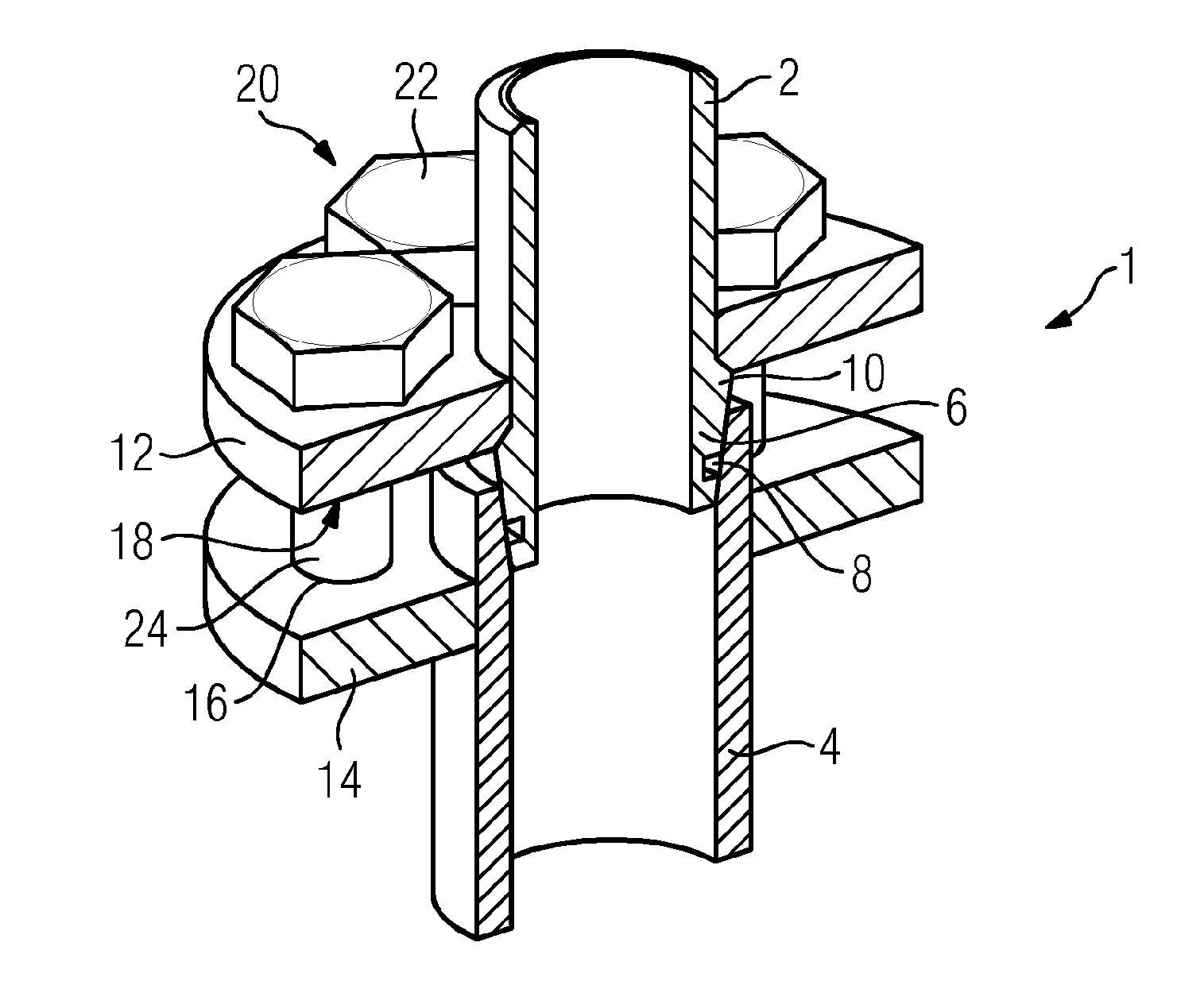
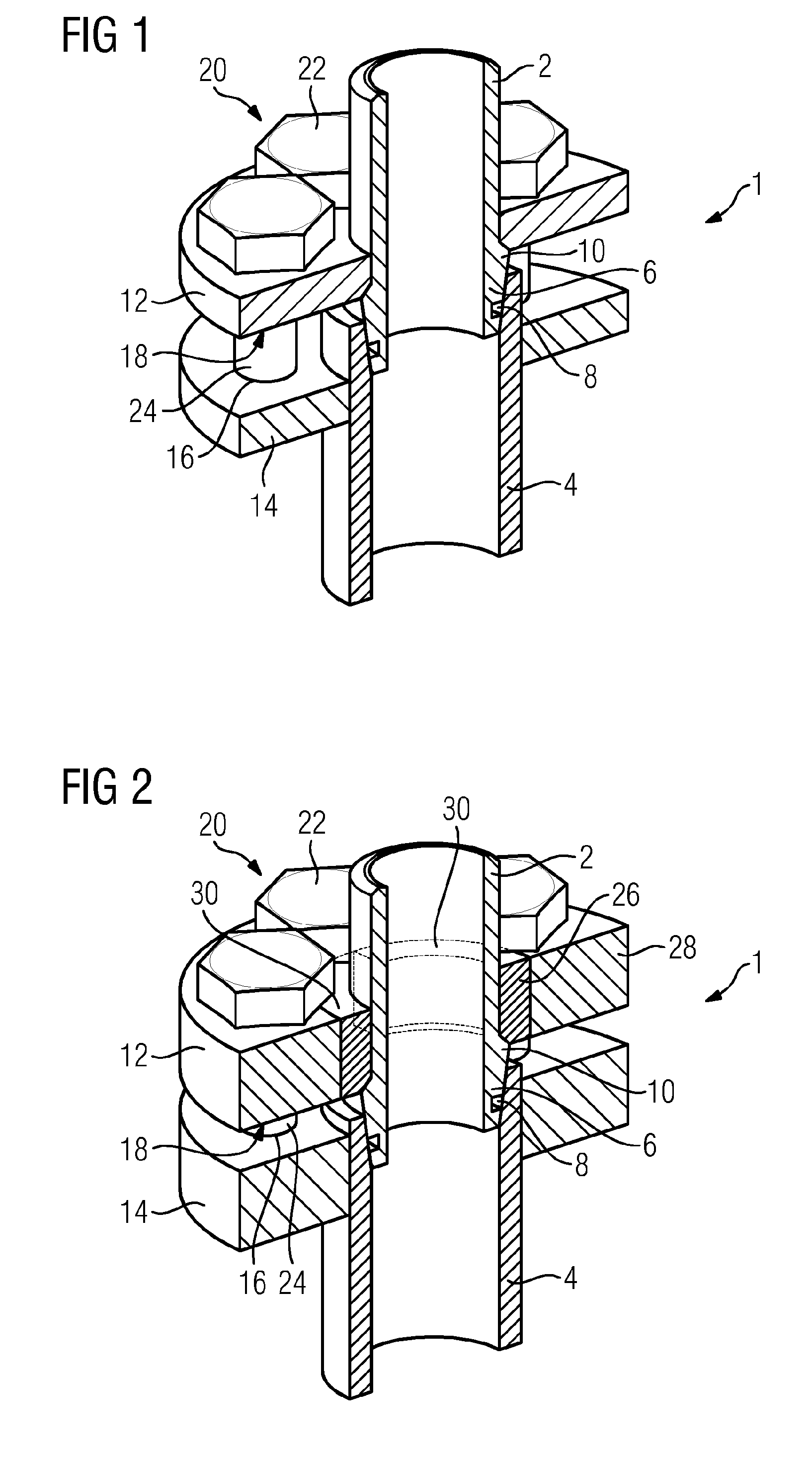
[0035]FIG. 1 shows a sectional view of a connecting system 1, which is not under any stress in the present case, for the detachable, sealed connection of a first pipe end 2 to a second pipe end 4. The pipe ends 2, 4 can also be ends of flexible hoses which are connected together, the term pipe end is therefore also to be understood as synonymous with the term hose end. Both pipe ends 2, 4 are hollow cylindrical. The first pipe end 2 comprises a concentrically connected sealing cone 6 which tapers toward the completion of the pipe end 2 so far that the outside diameter thereof is smaller than the inside diameter of the second pipe end 4. The first pipe end 2 with the sealing cone 6 can consequently be inserted concentrically into the second pipe end 4.

[0036]The sealing cone 6 additionally comprises a circumferential groove 8 into which a sealing material is inserted. The largest outside diameter of the sealing cone 6 is greater than the outside diameter of the remaining pipe end such...


PUM


Abstract

A connecting system for detachably connecting first pipe end to second pipe end, wherein first pipe end has sealing cone facing toward the second pipe end and a shoulder section. The connecting system includes first clamping disk, surrounding first pipe end and arranged on that side of the shoulder section which is averted from sealing cone, second clamping disk, surrounding and connected to second pipe end, and a multiplicity of screws, detachably connecting first clamping disk to second clamping disk. That section of first clamping disk which surrounds first pipe end is in the form of a separate circular disk ring which is detachably connected to the rest of the clamping disk, wherein the circular disk ring has multiple separate circular disk ring parts, and wherein the outer diameter of the circular disk ring is greater than the diameter of the shoulder section provided on the first pipe end.

Description

CROSS REFERENCE TO RELATED APPLICATIONS[0001]This application is the US National Stage of International Application No. PCT / EP2015 / 050480 filed Jan. 13, 2015, and claims the benefit thereof. The International Application claims the benefit of European Application No. EP14151885 filed Jan. 21, 2014. All of the applications are incorporated by reference herein in their entirety.FIELD OF INVENTION[0002]The invention relates to a connecting system for detachably connecting a first pipe end to a second pipe end, wherein the first pipe end comprises a sealing cone which faces the second pipe end and has a shoulder portion on its outside surface.BACKGROUND OF INVENTION[0003]Connecting systems of the named type are disclosed, for example, in DE 101 44 039 A1 under the designation of “cone sealing coupling”. They serve for detachably connecting two hollow cylindrical pipe ends. To this end, a rotationally symmetrical connection element, which is realized in a conical and hollow manner, is co...

Claims


Application Information

Patent Timeline
Patent Type & Authority Applications(United States)
IPC IPC(8): F16L23/028F16L21/04
CPCF16L21/04F16L23/0286
Inventor PIEDBOEUF, WOLFGANGRUDA, THOMAS
Owner SIEMENS AG
Why Eureka
Try Eureka