
Drilling fluid ph monitoring and control

a technology for monitoring and controlling ph in drilling fluid, which is applied in the direction of program control, borehole/well accessories, instruments, etc., can solve the problems of reducing the reliability and service life of downhole equipment, improper ph levels, and failure of downhole equipmen

Active Publication Date: 2017-10-26
BAKER HUGHES INC
View PDF14 Cites 6 Cited by
  • Summary
  • Abstract
  • Description
  • Claims
  • Application Information

AI Technical Summary

Benefits of technology

The present patent text describes techniques for monitoring and controlling the pH-value of a drilling fluid used in oil drilling operations. The techniques include sensing the pH-value and temperature of the drilling fluid before and after it is heated by a drilling fluid heater, and using a controller to determine the amount of additive to add to the drilling fluid to maintain a desired pH-value at the second temperature. These techniques help to maintain the effectiveness and stability of the drilling fluid during use in the wellbore, improving the overall efficiency and effectiveness of oil drilling operations.

Problems solved by technology

Demanding service conditions characterized by high temperature and corrosive environments (e.g., environments containing high chloride concentrations and / or corrosive gasses (e.g., CO2, H2S, etc.)) can significantly reduce the reliability and service life of downhole equipment.
Improper pH levels downhole contribute to corrosion such as pitting corrosion, environmentally assisted cracking (EAC), co-leaching, elastomers damage and secondary corrosion.
It should be appreciated that pH-excursions from a desired pH range of 8 to 12 can be the leading cause of downhole equipment failures or the cause of significant damage to drilling equipment.
This leads to costly non-productive time (NPT) and high repair costs.

Method used


Image

  • Drilling fluid ph monitoring and control
  • Drilling fluid ph monitoring and control
  • Drilling fluid ph monitoring and control

Examples


embodiment 1

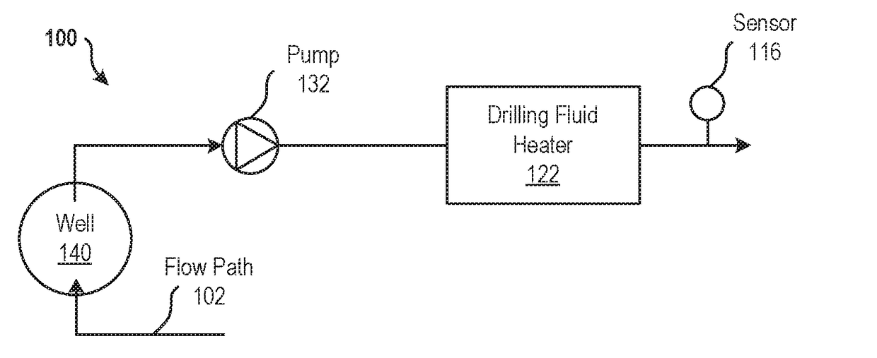
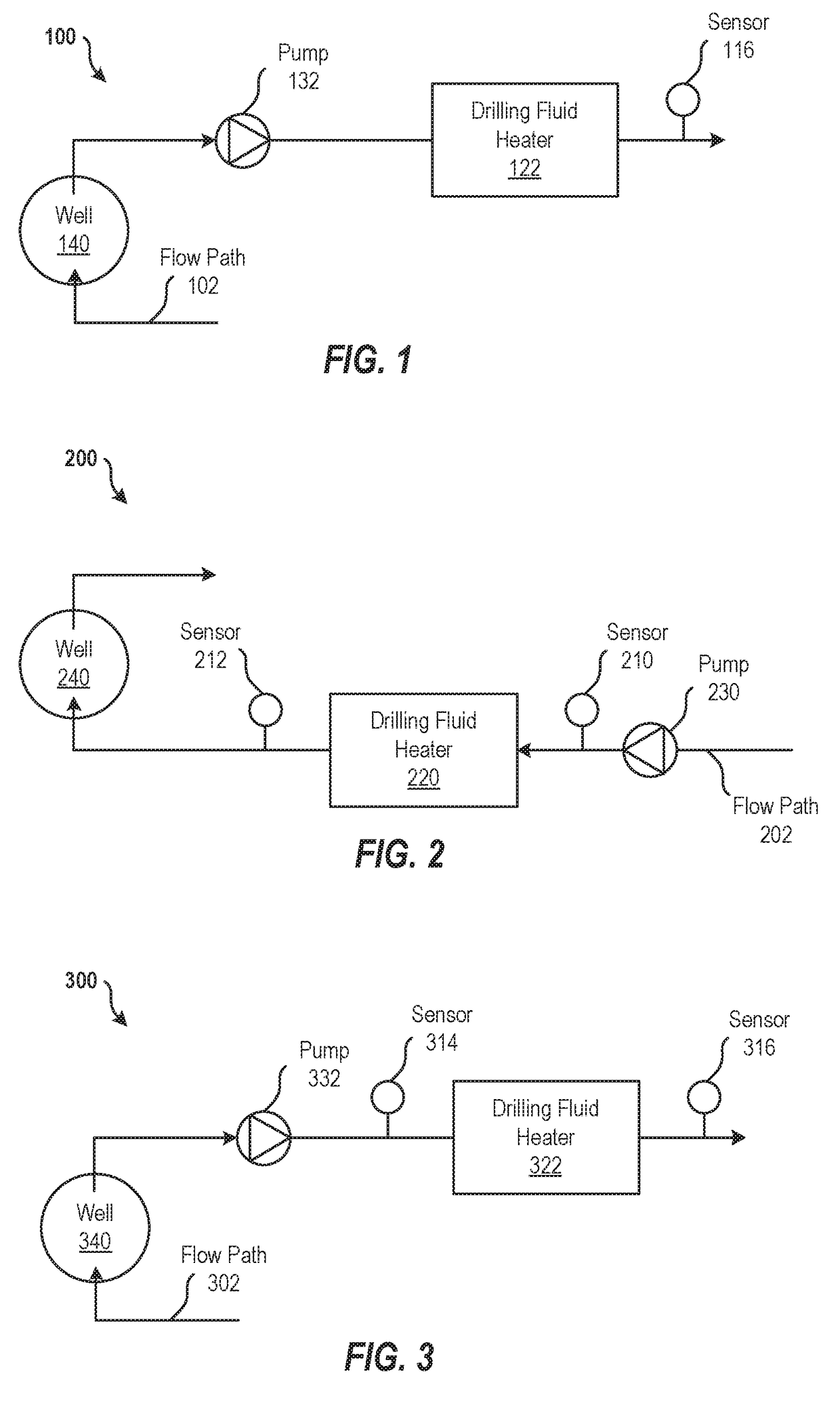
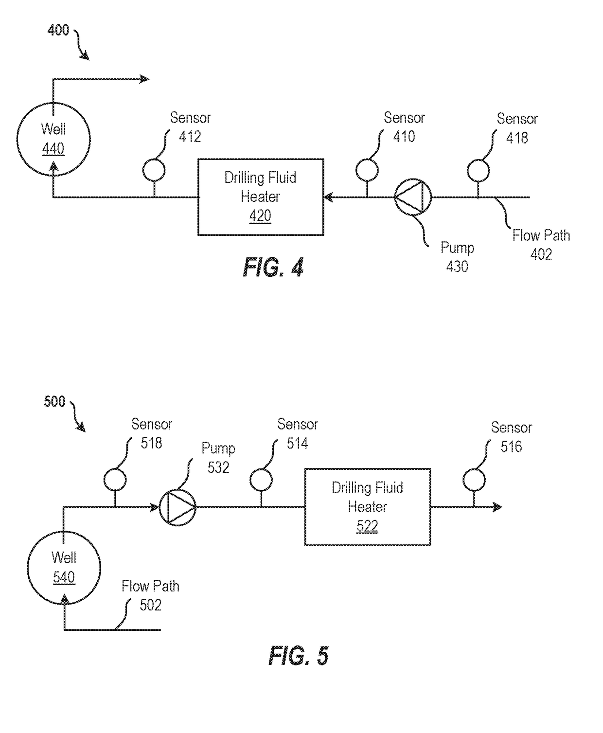
[0079] A system for monitoring and controlling the pH of a drilling fluid, the system comprising: a first sensor to sense a first pH-value and an associated first temperature of the drilling fluid prior to being heated by a drilling fluid heater; a second sensor to sense a second pH-value and an associated second temperature of the drilling fluid subsequent to being heated by the drilling fluid heater; and a controller comprising a memory having computer readable instructions and a processing device for executing the computer readable instructions, the computer readable instructions comprising: receiving the first pH-value and first temperature from the first sensor; receiving the second pH-value and second temperature from the second sensor; and determining an amount of additive to add to the drilling fluid to maintain a desired pH-value at the second temperature.

embodiment 2

[0080] The system of claim 1, wherein the second temperature is representative of an expected temperature downhole of a well.

embodiment 3

[0081] The system of claim 2, further comprising: the drilling fluid heater to heat the drilling fluid.


PUM


Abstract

Examples of techniques for monitoring and controlling the pH of a drilling fluid are disclosed. In one example implementation, a system may include a first sensor to sense a first pH-value and an associated first temperature of the drilling fluid prior to being heated by a drilling fluid heater and a second sensor to sense a second pH-value and an associated second temperature of the drilling fluid subsequent to being heated by the drilling fluid heater. The system may also include a controller comprising a memory having computer readable instructions and a processing device for executing the computer readable instructions. The computer readable instructions include receiving the first pH-value and first temperature from the first sensor, receiving the second pH-value and second temperature from the second sensor, and determining an amount of additive to add to the drilling fluid to maintain a desired pH-value at the second temperature.

Description

BACKGROUND[0001]The present disclosure relates to pH monitoring and, more particularly, to monitoring and controlling pH in drilling fluid.[0002]Boreholes are drilled into earth formations for the exploration and production of hydrocarbons, subterranean fluids, and minerals. During drilling operations components in the drillstring are in contact with the drilling fluid. Drilling fluids can be water or oil based but sometimes gaseous drilling fluids are also used. Drilling fluid properties are tailored to optimize drilling operations. The pH-value of drilling fluids, for instance, is typically controlled to maintain certain levels of corrosion protection to the metallic materials in the drillstring.[0003]Demanding service conditions characterized by high temperature and corrosive environments (e.g., environments containing high chloride concentrations and / or corrosive gasses (e.g., CO2, H2S, etc.)) can significantly reduce the reliability and service life of downhole equipment. Impro...

Claims


Application Information

Patent Timeline
Patent Type & Authority Applications(United States)
IPC IPC(8): G05B19/406E21B21/06
CPCG05B19/406E21B21/062G05B2219/45129G05B2219/32287E21B21/06
Inventor SARMIENTO-KLAPPER, HELMUTHOCHOA, BRIAN
Owner BAKER HUGHES INC
Learn More