Apparatus and method to reduce fluid pressure in a wellbore

a technology of fluid pressure reduction and fluid flow, which is applied in the direction of borehole/well accessories, drilling rods, drilling pipes, etc., can solve the problems of inability to drill deep wellbores, damage to a formation and loss of expensive drilling fluid, and the path of hydrocarbons at a lower portion of the wellbore becomes very restricted, so as to improve the movement of cuttings, reduce friction head associated, and improve the effect of viscosity

Inactive Publication Date: 2005-01-04
WEATHERFORD TECH HLDG LLC
View PDF25 Cites 132 Cited by
  • Summary
  • Abstract
  • Description
  • Claims
  • Application Information

AI Technical Summary

Benefits of technology

In another aspect, the invention provides means to use viscous drilling fluid to improve the movement of cuttings. By reducing the friction head associated with the circulating fluid, a higher viscosity fluid can be used to facilitate the movement of cuttings towards the surface of the well.
In a further aspect of the invention, the tool provides means for underbalanced or near-balanced drilling of ERD wells. ERD wells are conventionally drilled overbalanced with wellbore pressure being higher than pore pressure in order to maintain control of the well. Drilling fluid weight is selected to ensure that a hydraulic head is greater than pore pressure. An ECD reduction tool permits the use of lighter drilling fluid so that the well is underbalanced in static condition and underbalanced or nearly-underbalanced in flowing condition.
In yet a further aspect of the invention, the apparatus provides a method to improve the rate of penetration (ROP) and the formation of a wellbore. This advantage is derived from the fact t

Problems solved by technology

Excessive fluid pressure in the wellbore can result in damage to a formation and loss of expensive drilling fluid.
Presently, however, so many casing strings are necessary in extended reach deep (ERD) wellbores that the path for hydrocarbons at a lower portion of the wellbore becomes very restricted.
In some instances, deep wellbores are impossible to drill due to the number casing of strings necessary to complete the well.
Another problem associated with deep wellbores is differential sticking of a work string in the well.
If wellbore fluid enters an adjacent formation, the work string can be pulled in the direction of the exiting fluid due to a pressure differential between pore and

Method used


Image

  • Apparatus and method to reduce fluid pressure in a wellbore
  • Apparatus and method to reduce fluid pressure in a wellbore
  • Apparatus and method to reduce fluid pressure in a wellbore

Examples


Embodiment Construction

The present invention relates to apparatus and methods to reduce the pressure of a circulating fluid in a wellbore. The invention will be described in relation to a number of embodiments and is not limited to any one embodiment shown or described.

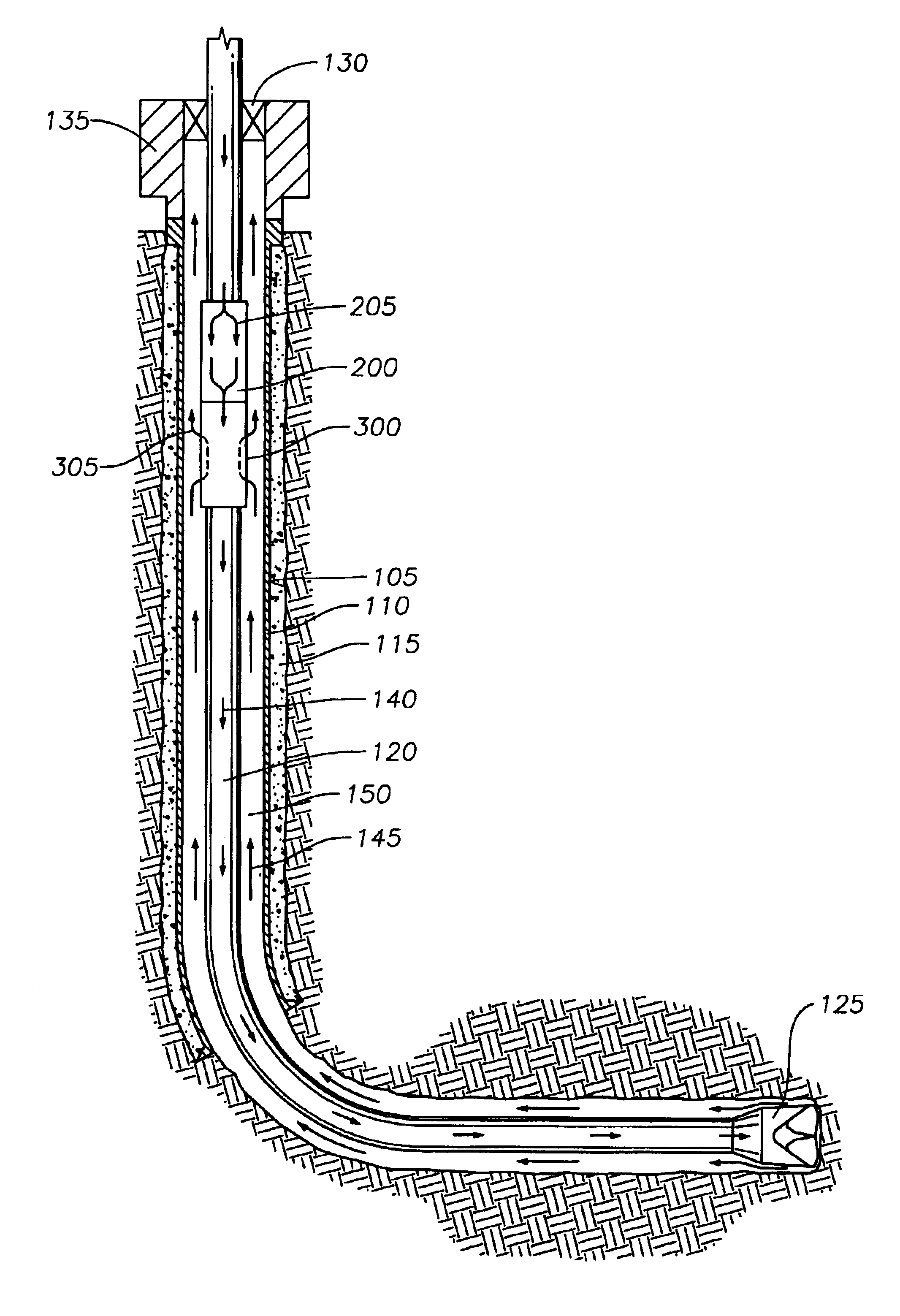
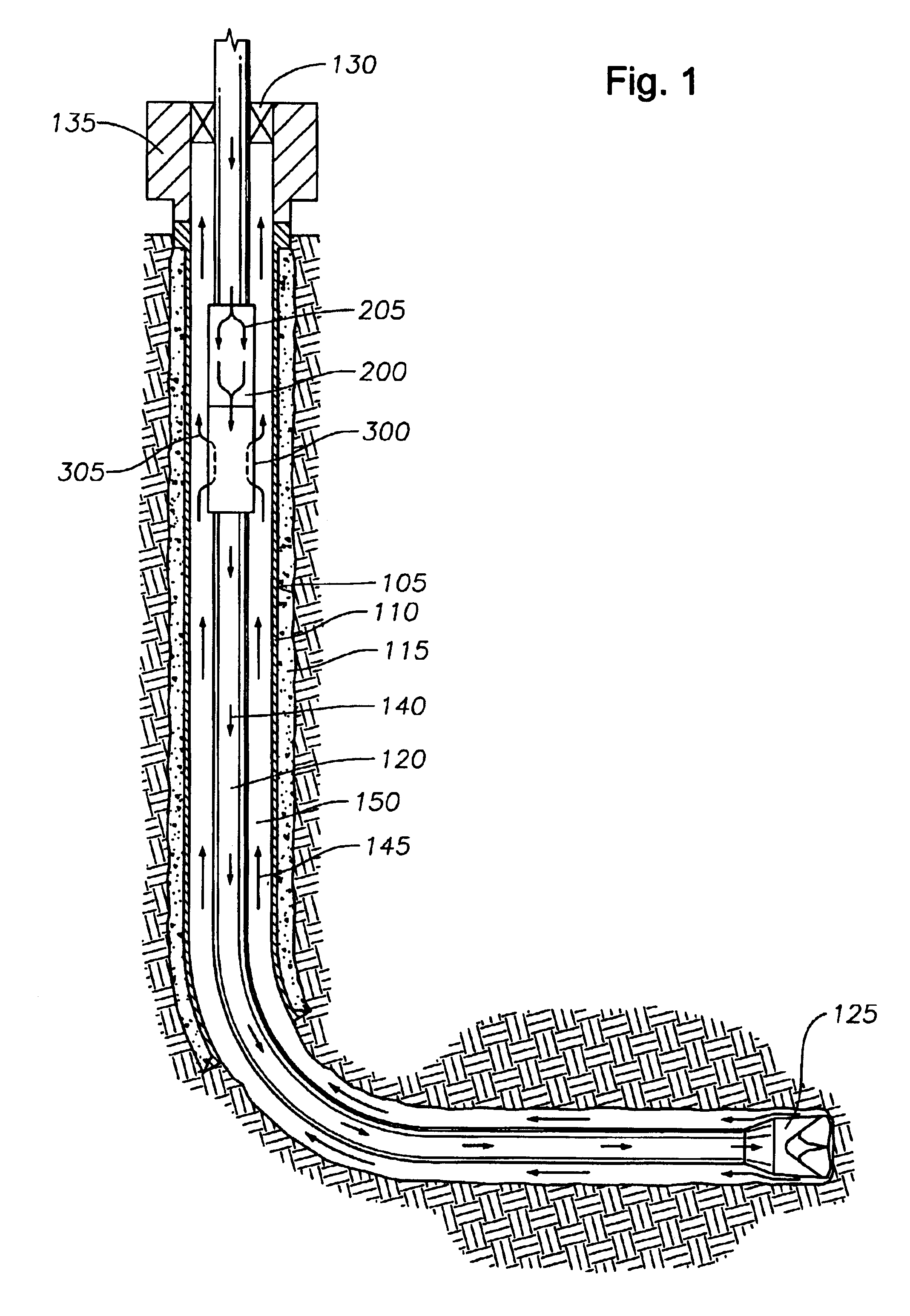
FIG. 1 is a section view of a wellbore 105 including a central and a horizontal portion. The central wellbore is lined with casing 110 and an annular area between the casing and the earth is filled with cement 115 to strengthen and isolate the wellbore 105 from the surrounding earth. At a lower end of the central wellbore, the casing terminates and the horizontal portion of the wellbore is an “open hole” portion. Coaxially disposed in the wellbore is a work string 120 made up of tubulars with a drill bit 125 at a lower end thereof. The bit rotates at the end of the string 120 to form the borehole and rotation is either provided at the surface of the well or by a mud motor (not shown) located in the string 120 proximate the drill bit 125. In...


PUM


Abstract

The present invention generally provides apparatus and methods for reducing the pressure of a circulating fluid in a wellbore. In one aspect of the invention an ECD (equivalent circulation density) reduction tool provides a means for drilling extended reach deep (ERD) wells with heavyweight drilling fluids by minimizing the effect of friction head on bottomhole pressure so that circulating density of the fluid is close to its actual density. With an ECD reduction tool located in the upper section of the well, the friction head is substantially reduced, which substantially reduces chances of fracturing a formation.

Description

BACKGROUND OF THE INVENTION1. Field of the InventionThe present invention relates to reducing pressure of a circulating fluid in a wellbore. More particularly, the invention relates to reducing the pressure brought about by friction as the fluid moves in a wellbore. More particularly still, the invention relates to controlling and reducing downhole pressure of circulating fluid in a wellbore to prevent formation damage and loss of fluid to a formation.2. Description of the Related ArtWellbores are typically filled with fluid during drilling in order to prevent the in-flow of production fluid into the wellbore, cool a rotating bit, and provide a path to the surface for wellbore cuttings. As the depth of a wellbore increases, fluid pressure in the wellbore correspondingly increases developing a hydrostatic head which is affected by the weight of the fluid in the wellbore. The frictional forces brought about by the circulation of fluid between the top and bottom of the wellbore create ...

Claims


Application Information

Patent Timeline
IPC IPC(8): E21B21/00E21B21/08E21B4/02
CPCE21B4/02E21B21/08E21B21/00E21B2021/006E21B21/085
Inventor HOSIE, DAVIDBANSAL, RAMKUMAR K.MOYES, PETER B.
Owner WEATHERFORD TECH HLDG LLC
Why Eureka
Try Eureka