Injection molding method and injection molding machine

a technology of injection molding machine and injection molding method, which is applied in the direction of coatings, etc., can solve the problems of increased cost of raw materials, difficulty in opening fiber bundles, and considerable cost of twin-shaft extruders, and achieve the effect of uneven distribution of reinforcing fibers

Active Publication Date: 2017-11-02
MITSUBISHI HEAVY IND LTD +1
View PDF2 Cites 8 Cited by
  • Summary
  • Abstract
  • Description
  • Claims
  • Application Information

AI Technical Summary

Benefits of technology

[0025]According to the present invention, it is possible to provide the injection molding method and the injection molding machine in which uneven distribution of the reinforcing fibers can be eliminated without applying an excessive shearing force to the reinforcing fibers and by using a simple single-shaft plasticizing screw, even in generation of the molten resin, in which the added components, particularly the reinforcing fibers and the resin raw material are supplied to the inside of the cylinder.

Problems solved by technology

However, since the expensive master batch is used as a raw material, the raw material cost increases.
However, in the direct raw material supply-type injection molding machine, since distribution mixing and dispersion mixing of the added components in the thermoplastic resin are insufficient, an injection molding machine in which the problems are improved has been proposed (PTL 1).
Accordingly, it is not easy to open a fiber bundle which is an aggregation of the reinforcing fibers and to disperse the fibers into the resin.
However, the twin-shaft extruder is considerably expensive, and handling such as selecting the molding conditions and retaining the machine is complicated.
Thus, it is not easy to perform molding (PTL and PTL 2).
However, the bundle or the lump (hereinafter, will be generically named as the bundle) of the reinforcing fibers still has not been solved.
Particularly, in a case of a high content rate such that the content of the reinforcing fibers is equal to or greater than 10%, it is difficult to uniformly disperse the reinforcing fibers in the resin.

Method used


Image

  • Injection molding method and injection molding machine
  • Injection molding method and injection molding machine
  • Injection molding method and injection molding machine

Examples


Embodiment Construction

[0041]Hereinafter, the present invention will be described in detail based on an embodiment illustrated in the accompanying drawings.

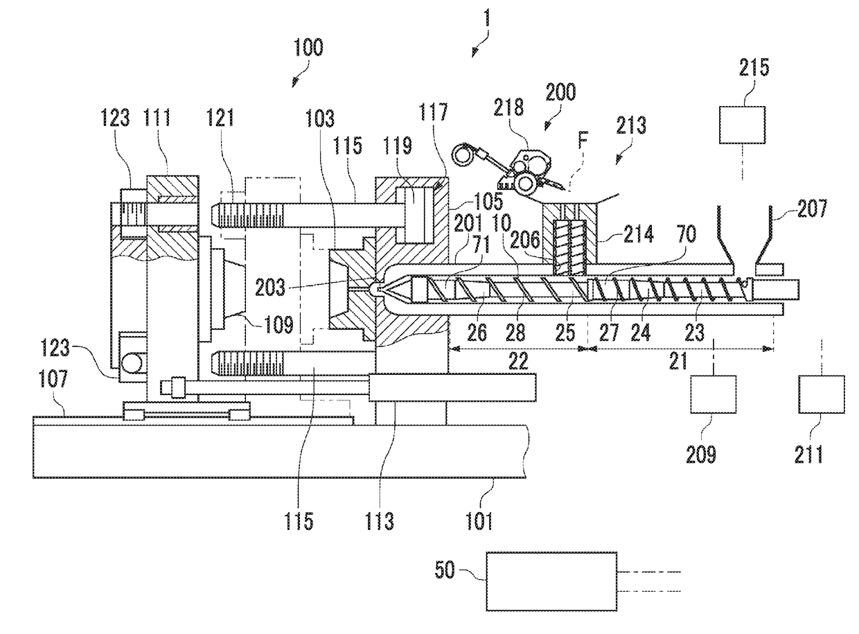
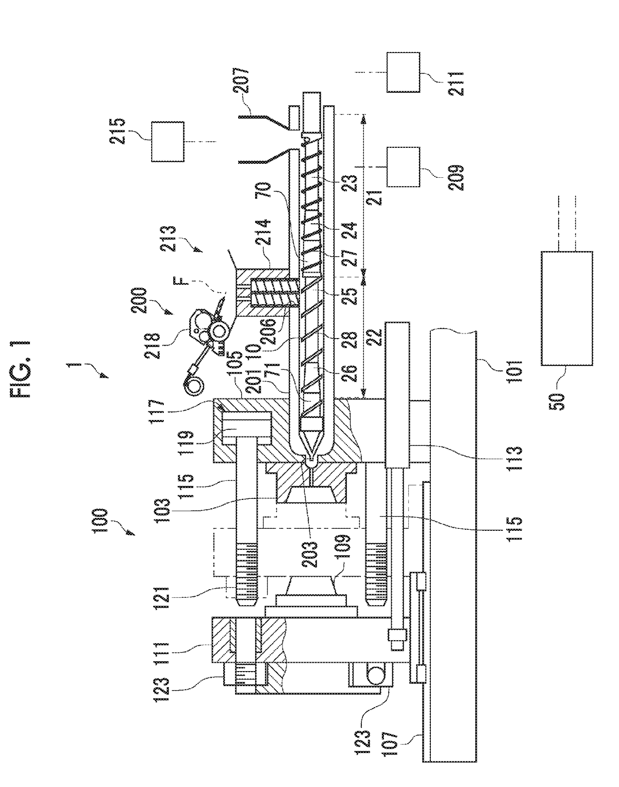
[0042]As illustrated in FIG. 1, an injection molding machine 1 according to the present embodiment includes a mold clamping unit 100, a plasticizing unit 200, and a control section 50 which controls operations of the units.

[0043]Hereinafter, the outline of the configuration and the operation of the mold clamping unit 100, and the configuration and the operation of the plasticizing unit 200 will be described. Subsequently, the procedure of injection molding performed by the injection molding machine 1 will be described.

Configuration of Mold Clamping Unit

[0044]The mold clamping unit 100 includes a stationary platen 105 which is fixed to the top of a base frame 101 and to which a fixed mold 103 is attached, a movable platen 111 which moves the lateral direction of the view on a slide member 107 such as a rail and a slide plate due to an operation of a hyd...


PUM

PropertyMeasurementUnit
lengthsaaaaaaaaaa
pressureaaaaaaaaaa
velocityaaaaaaaaaa

Abstract

Provided is an injection molding method for resin that contains reinforcing fiber, the method being capable of easily eliminating uneven distribution of added components. The injection molding method is provided with: a plasticizing step for supplying resin pellets P and added components to a cylinder equipped with a screw 10, which has a rotating axis as the center is capable of rotating normally and in reverse, and generating molten resin by rotating the screw 10 in the normal direction; and an injecting step for injecting the molten resin M comprising the added components into a cavity. In the plasticizing step, a reverse rotation operation for reversing the rotation of the screw 10 is performed or a screw-stopping operation of stopping the normal rotation of the screw 10 is performed with a prescribed timing and for a prescribed period.

Description

TECHNICAL FIELD[0001]The present invention relates to injection molding for a resin that contains an added component, for example, a reinforcing fiber.BACKGROUND ART[0002]A high value molded product in which the strength and the function are enhanced by containing added components is used for various purposes. As a technique of acquiring the molded product through injection molding, there is a known technique in which a thermoplastic resin is molten due to the rotation of a screw inside a cylinder configuring a plasticizing apparatus, and after the added components are mixed or kneaded therewith, the result is injected into a mold of an injection molding machine.[0003]In a case where the added components such as additives and a filling substance are mixed and kneaded with the thermoplastic resin and injection molding of a desired molded product is performed, usually, a master batch pellet which is produced by a twin-shaft extrusion molding machine and contains the added components i...

Claims


Application Information

Patent Timeline
Patent Type & Authority Applications(United States)
IPC IPC(8): B29C45/00B29C45/50B29C45/76
CPCB29C45/0005B29C45/50B29C45/76B29C2945/76832B29C2945/76665B29C2945/76826B29C2945/76605B29B7/484B29B7/60B29B7/90B29B7/905B29C45/1816
Inventor NOBUTA, MUNEHIROTODA, NAOKIKARIYA, TOSHIHIKOYAMAGUCHI, TAKESHIKINOSHITA, KIYOSHI
Owner MITSUBISHI HEAVY IND LTD
Why Eureka
Try Eureka