
Analysis and Evaluation of a Practical Downlink Multiuser MIMO Scheduler over LTE Advanced Massive MIMO Systems

a multi-user, multi-input multi-output technology, applied in the direction of channel coding adaptation, transmission path sub-channel allocation, wireless communication, etc., can solve the problems of not meeting the expectations of mu-mimo in frequency-division duplexing (fdd) systems equipped with a modest number of transmit antennas (typically 2 or 4) and obtaining csi feedback that is accurate enough for mu-mimo, etc., to achieve enhanced long-term evolution scheduling

Active Publication Date: 2017-11-02
NEC CORP
View PDF2 Cites 0 Cited by
  • Summary
  • Abstract
  • Description
  • Claims
  • Application Information

AI Technical Summary

Benefits of technology

This patent is about a system that helps improve the way resources are assigned to users in a mobile communication network. The system uses a ranked list of users and assigns a special code to each user, based on their needs. It then generates a new list based on these special codes, which reduces the number of computations needed for the users. The system also adapts to the needs of users in real-time, making the most efficient use of network resources. Overall, this system helps improve the performance and reliability of mobile networks.

Problems solved by technology

Moreover, none of the prior algorithms incorporate the decorrelation property of massive MIMO systems.
However, the performance results of MU-MIMO in frequency-division duplexing (FDD) systems equipped with a modest number of transmit antennas (typically 2 or 4) have not lived up to the expectations.
This is because obtaining CSI feedback that is accurate enough for MU-MIMO has proved to be challenging given the feedback constraints placed in LTE.
Moreover, the small number of transmit antennas that comprise of cross-polarized antenna element pairs are useful for single-user (SU) MIMO but are not conducive to creating beams that enable good separation of different users in the signal space.

Method used


Image

  • Analysis and Evaluation of a Practical Downlink Multiuser MIMO Scheduler over LTE Advanced Massive MIMO Systems
  • Analysis and Evaluation of a Practical Downlink Multiuser MIMO Scheduler over LTE Advanced Massive MIMO Systems
  • Analysis and Evaluation of a Practical Downlink Multiuser MIMO Scheduler over LTE Advanced Massive MIMO Systems

Examples


Embodiment Construction

[0015]The invention improves the DL MU-MIMO scheduler for LTE advanced massive MIMO systems. Different embodiments can be used singly or in combination together. Several useful embodiments include: (i) processing the output to enforce finite modulation and coding scheme (MCS) and finite buffer constraints; (ii) incorporating hybrid automatic repeat request (HARQ) and (iii) including complexity reduction features that also exploit the decorrelating property of massive MIMO systems.

[0016]An embodiment considers the DL wideband MU-MIMO scheduling problem in each cell of an LTE-A network, where a scheduling decision must be determined every sub-frame. This involves selecting users on each narrowband resource block (RB), where a selected user can be assigned more than one stream (a.k.a. a transmit rank greater than 1). However, there is a coupling constraint in that a user that is selected on multiple RBs must be assigned the same transmit rank on all those RBs. It is noted that the flex...


PUM


Abstract

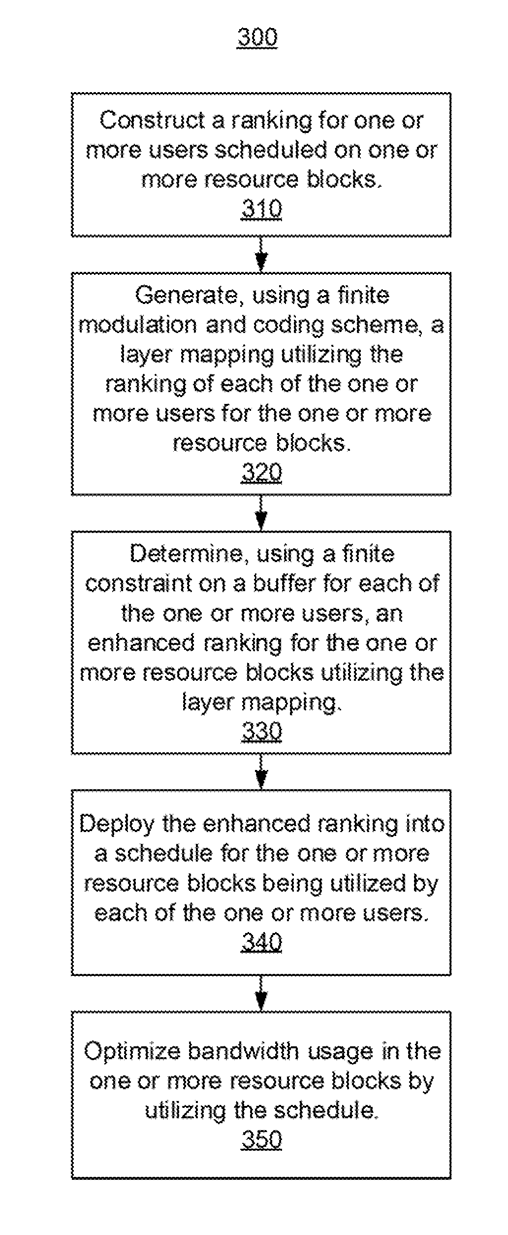
Methods and a system are provided for enhanced long-term evolution scheduling. A ranking is constructed for one or more users scheduled on one or more resource blocks. A layer mapping is generated, using a finite modulation and coding scheme, utilizing the ranking of each of the one or more users for the one or more resource blocks. An enhanced ranking is determined, using a finite constraint on a buffer for each of the one or more users, for the one or more resource blocks utilizing the layer mapping. The enhanced ranking is deployed into a schedule for the one or more resource blocks being utilized by each of the one or more users. Bandwidth usage is optimized in the one or more resource blocks by utilizing the schedule.

Description

RELATED APPLICATION INFORMATION[0001]This application claims priority to U.S. Provisional Patent Application Ser. No. 62 / 329,411 filed on Apr. 29, 2016, incorporated herein by reference in its entirety.BACKGROUNDTechnical Field[0002]The present invention generally relates to long-term evolution (LTE) systems and more particularly to a practical downlink (DL) multiuser multi-input-multi-output (MU-MIMO) scheduler over LTE advanced massive MIMO systems.Description of the Related Art[0003]The MU-MIMO narrowband user selection problem has been analyzed mainly for the case when each user has one receive antenna and can be assigned one stream. In general, there is a coupling constraint in that a user that is selected on multiple resource blocks (RBs) must be assigned the same transmit rank on all those RBs, a.k.a. per-user rank constraint. The DL wideband MU-MIMO scheduling problem with the aforementioned per-user rank-constraint has been only considered for specific values of the input p...

Claims


Application Information

Patent Timeline
Patent Type & Authority Applications(United States)
IPC IPC(8): H04W72/12H04W72/06H04W28/02H04L5/00H04L1/18H04B7/0452
CPCH04W72/1247H04W72/06H04W72/1273H04W72/1231H04W72/121H04L1/1893H04B7/0452H04L5/0026H04W28/0215H04L5/0023H04L5/0037H04L1/1822H04L1/1887H04W72/542H04W72/566H04L1/0009
Inventor PRASAD, NARAYANRANGARAJAN, SAMPATHWELLS, PATRICIAARNOTT, ROBERT
Owner NEC CORP
Learn More