Support for a radio equipment of an aircraft, radio system and aircraft

a radio equipment and aircraft technology, applied in the direction of fuselage, antenna adaptation in movable bodies, transportation and packaging, etc., can solve the problems of aircraft sliding conditions, radar volume interference with ground, and system is not fully satisfactory, so as to reduce the interference of radio equipment

Active Publication Date: 2017-11-09
DASSAULT AVIATION
View PDF15 Cites 6 Cited by
  • Summary
  • Abstract
  • Description
  • Claims
  • Application Information

AI Technical Summary

Benefits of technology

[0013]One aim of the invention is therefore to resolve these drawbacks, in particular to propose a support device for a piece of radio equipment such as a radar that makes it possible to minimize the interference of the radio equipment with the ground during emergency landing and that can be installed on an aircraft independently of the primary structure of this aircraft, and without major modification of the primary structure.

Problems solved by technology

These pieces of equipment cannot, however, be integrated into the cell of the aircraft due to radio disruptions caused by the cell.
In particular, during emergency landing, the landing gear being retracted, the volume of the radar interferes with the ground and modifies the sliding conditions of the aircraft, relative to an aircraft that does not have such a radar.
However, such a system is not fully satisfactory.
In particular, the system must be positioned in an unpressurized space, and is not compatible with the configuration of the pressurized cabin of certain types of aircraft, situated just above the radar.
Furthermore, such a system requires a major modification of the primary structure of the aircraft, which makes it impossible to redevelop an existing aircraft in order to incorporate this system therein.
Furthermore, the necessary use of a hydraulic or electric energy source to deploy the platform, as well as various associated cases, control valves and sensors, makes this solution complex to implement.
Additionally, all of these elements include failure risks, accentuated by the fact that the elevator system is activated during each mission.
Maintenance of the system may therefore prove complex and costly.

Method used


Image

  • Support for a radio equipment of an aircraft, radio system and aircraft
  • Support for a radio equipment of an aircraft, radio system and aircraft
  • Support for a radio equipment of an aircraft, radio system and aircraft

Examples


Embodiment Construction

[0042]The orientation terms used below will be terms associated with the usual plane of reference for aircraft, shown in the figures, and which comprises:[0043]a longitudinal direction X, oriented from front to back,[0044]a transverse direction Y, perpendicular to the longitudinal direction X and oriented from left to right, and[0045]a vertical direction Z, perpendicular to the horizontal plane defined by the longitudinal X and transverse Y directions and oriented from bottom to top.

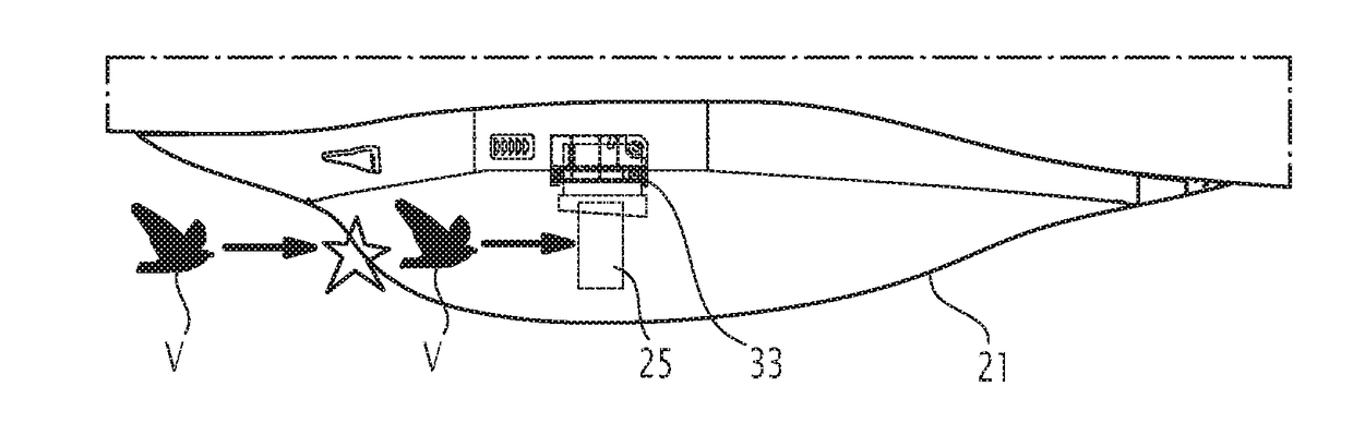
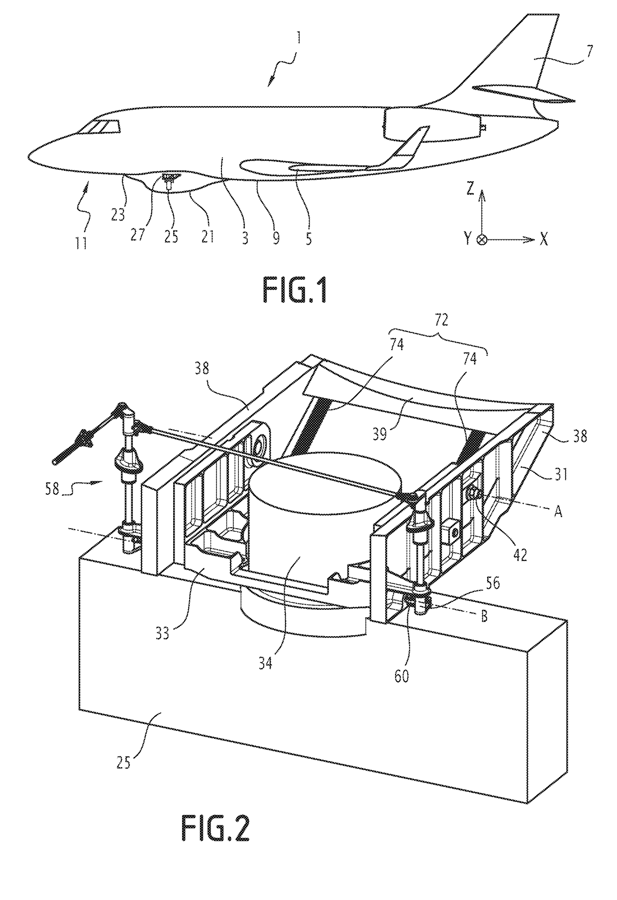
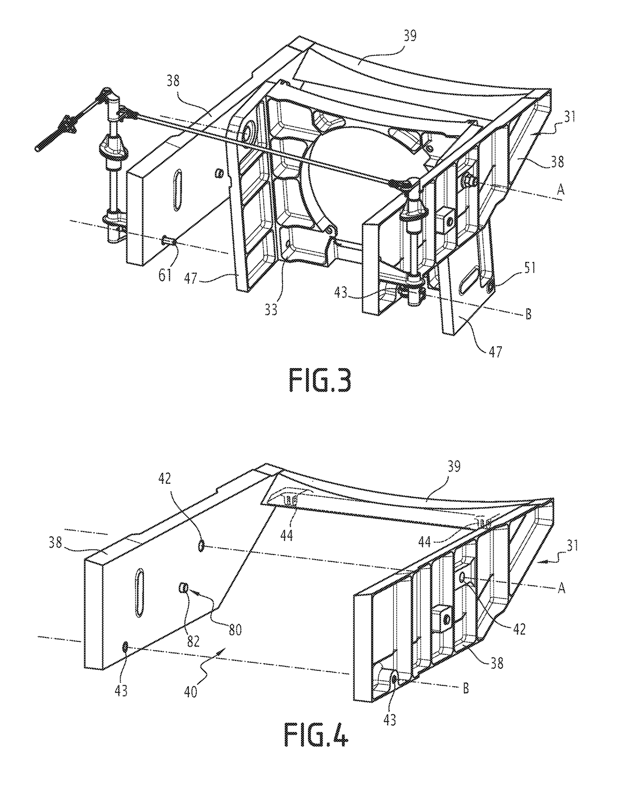
[0046]FIG. 1 illustrates an aircraft 1 according to one embodiment. This aircraft 1, which is an airplane in the illustrated example, comprises a fuselage 3, elongated in the longitudinal direction of the aircraft 1, an airfoil 5, an empennage 7, a wing root fairing 9, for connecting the airfoil 5 to the fuselage 3. The aircraft 1 also includes a front landing gear, which is retracted and thus not visible in FIG. 1, but the location of which is indicated by general reference 11.

[0047]The aircraft 1 also ...


PUM


Abstract

A support device for a radio equipment of an aircraft, radio system and aircraft are provided. The support device includes a fastening structure (31), intended to be secured to a lower surface of a fuselage of an aircraft, and a support platform (33) of the radio equipment (25). The support platform (33) is mounted pivoting on the fastening structure (31) around a pivot axis (A) between an operational position and a backup position. The support device comprises a locking mechanism (56), able to be actuated from a locked configuration, in which said locking mechanism (56) keeps the support platform (33) in its operational position while preventing any pivoting of the support platform (33), to an unlocked configuration, in which the locking mechanism (56) allows the support platform (33) to pivot relative to the fastening structure (31).

Description

[0001]This claims the benefit of French Patent Application FR 16 00733, filed May 3, 2016 and hereby incorporated by reference herein.[0002]The present invention relates to a support device for a radio equipment of an aircraft, the support device comprising:[0003]a fastening structure, configured to be secured to a lower surface of a fuselage of an aircraft,[0004]a support platform for the radio equipment, configured to receive the radio equipment.[0005]It in particular relates to a support device for a ventral radar of an aircraft, i.e., a radar mounted on a lower surface of the fuselage of the aircraft.BACKGROUND[0006]Aircraft are generally provided with pieces of radio equipment that can be intended for the communication of the aircraft, such as antennas, or the observation of the aircraft's environment, such as radars. These pieces of equipment cannot, however, be integrated into the cell of the aircraft due to radio disruptions caused by the cell.[0007]It has thus been proposed...

Claims


Application Information

Patent Timeline
Patent Type & Authority Applications(United States)
IPC IPC(8): B64D47/00B64C1/36B64D45/00
CPCB64D47/00B64D2045/0095B64D45/00B64C1/36H01Q1/28H01Q1/125H01Q1/42H01Q3/06
Inventor TABUTEAU, JEROMEBRUNET, JEROME
Owner DASSAULT AVIATION
Why Eureka
Try Eureka