Valve device

Active Publication Date: 2017-11-09
DENSO CORP
View PDF4 Cites 3 Cited by
  • Summary
  • Abstract
  • Description
  • Claims
  • Application Information

AI Technical Summary

Benefits of technology

The present invention aims to address the issue of burnout of electric actuators and improve the performance of valve positioning systems. The invention reduces the load on the valve urging part, which results in lower power requirements for the electric actuator and prevents burnout. Consequently, the invention provides greater flexibility for positioning the valve in relation to the switch position. In summary, the invention fulfills both requests: reducing the load on the valve and ensuring accurate positioning after an IG switch is turned off.

Problems solved by technology

In the case of a valve device that has to maintain a valve at a fully-closed position for a long period of time in particular, an actuator may burn out disadvantageously if the urging force of an opening spring and a resistance force are large.
When the urging force of an opening spring is reduced however, a valve cannot return to a predetermined intermediate position only by the urging force of the opening spring and stops disadvantageously at a position on the closed side of the intermediate position.
When an intermediate position is set as a position allowing a valve to be restrained from freezing and sticking, the valve may freeze and stick disadvantageously if the valve can return only to a position on the closed side of the intermediate position.

Method used


Image

  • Valve device
  • Valve device
  • Valve device

Examples


Embodiment Construction

[0033]The present disclosure is explained in detail by the following embodiment.

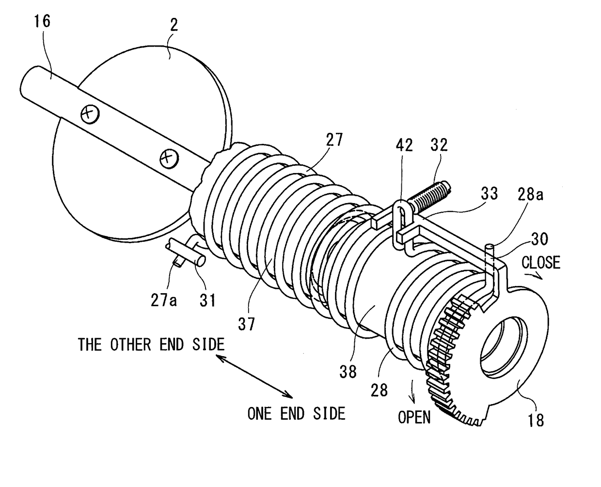
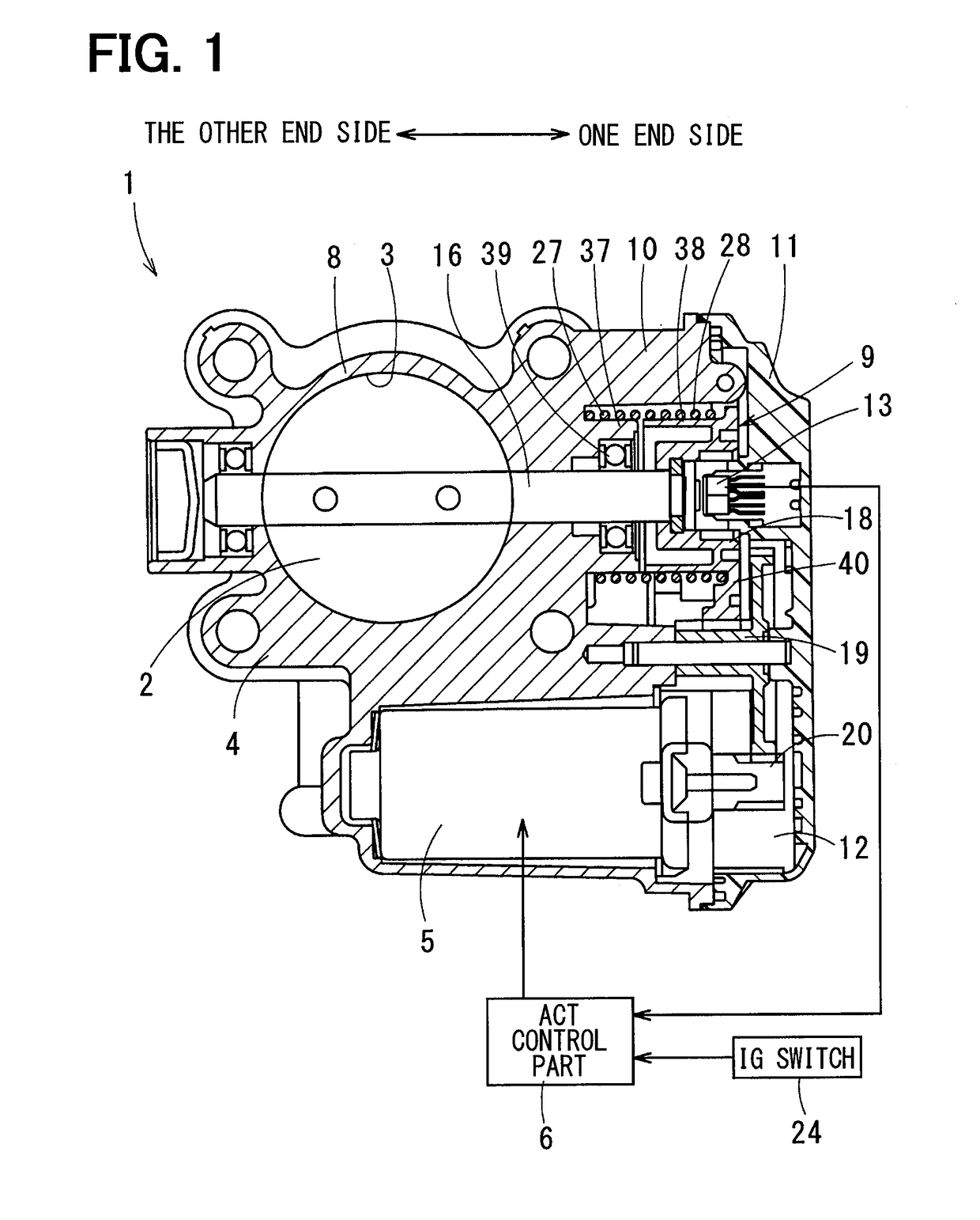
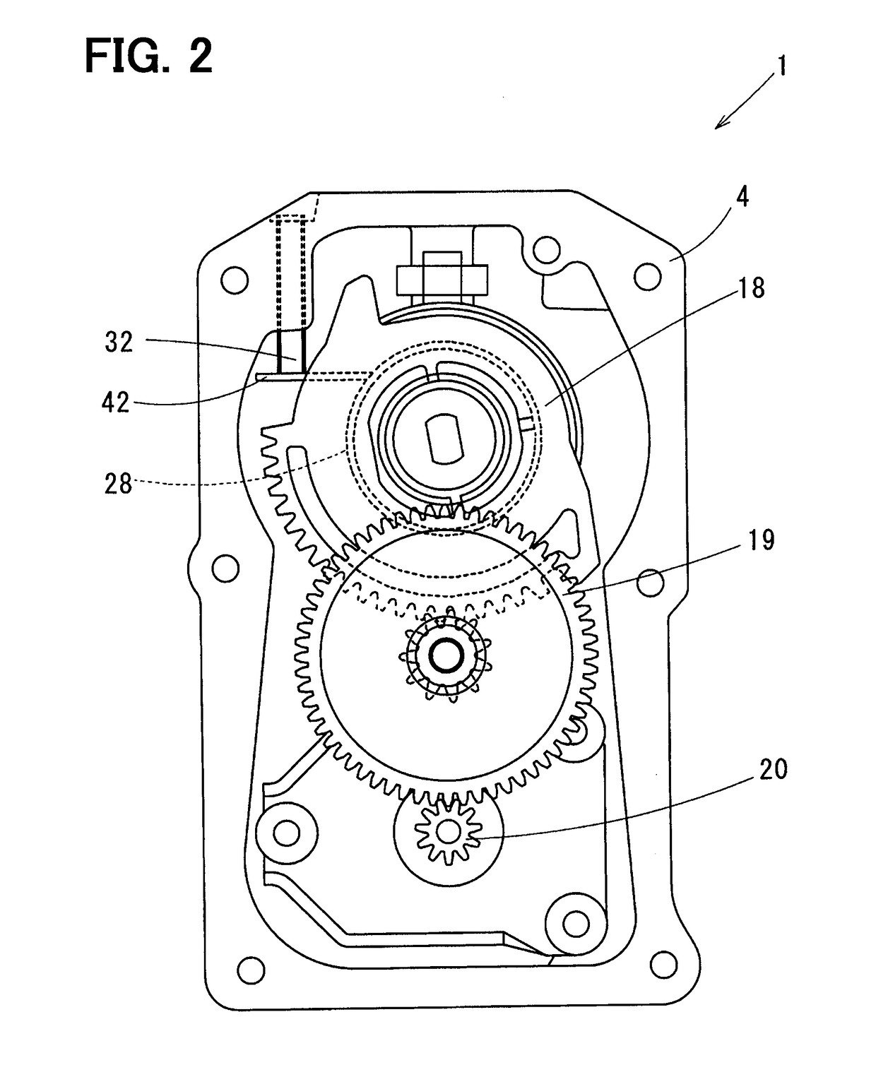
[0034]The configuration of an embodiment is described hereunder. A valve device 1 according to the present embodiment is explained in reference to FIGS. 1 to 9. The valve device 1 according to the present embodiment is a throttle valve device for a diesel engine and is a valve device for adjusting an intake air mass fed to a combustion chamber in an internal-combustion engine.

[0035]The valve device 1 has: a valve 2 of a butterfly valve type driven in response to an accelerator manipulative variable by a driver; a body 4 forming an intake path 3 to an internal-combustion engine and containing the valve 2; a motor 5 to drive the valve 2; and an ACT control part 6 to control the drive of the motor 5.

[0036]The body 4 is made of a metal and has a cylinder part 8 forming the intake path 3 and containing the valve 2 and a gear housing part 10 containing a reduction gear 9 to transfer the driving force of the mo...


PUM


Abstract

An electrically-operated actuator rotates a valve toward its closing side or opening side. A valve urging part urges the valve from a fully-closed position toward the opening side. An ACT control part controls the electrically-operated actuator to drive. A set load of the valve urging part is smaller than a set load that is capable of returning the valve from a fully-closed position to an intermediate position only by urging force of the valve urging part. When a position of the valve at time of turning off an IG switch for stopping operation of an internal-combustion engine is on the closing side of the intermediate position, the ACT control part shifts the valve to the intermediate position by the electrically-operated actuator after the IG switch is turned off.

Description

CROSS REFERENCE TO RELATED APPLICATION[0001]This application is based on Japanese Patent Application No. 2014-235685 filed on Nov. 20, 2014, the disclosure of which is incorporated herein by reference.TECHNICAL FIELD[0002]The present disclosure relates to a valve device to open and close a fluid flow path communicating with a combustion chamber in an internal-combustion engine.BACKGROUND ART[0003]A valve device having a body forming a fluid flow path communicating with a combustion chamber in an internal-combustion engine and a valve supported pivotably in the body and driven by an actuator has been conventionally known. As such a valve device, a throttle valve device that can change an intake air mass fed to a combustion chamber, an EGR valve device that can change an exhaust gas mass recirculated from an exhaust path to an intake path, or the like is named.[0004]Then as a valve device, a valve device of a W spring structure having a spring loading an open side urging force on a va...

Claims


Application Information

Patent Timeline
IPC IPC(8): F02D9/02F16K1/22F02M35/10F02D41/14F16K31/04F02D9/04
CPCF02D9/02F16K31/041F16K1/22F02D2009/0213F02M35/10393F02D41/1493F02D9/04F02D11/10F02D2011/103F02D2011/108
Inventor FUJINAKA, YUUTAKOBAYASHI, TAKASHISASAKI, KAZUSHI
Owner DENSO CORP
Why Eureka
Try Eureka