Vacuum pressure booster

Inactive Publication Date: 2009-06-23
AUTOLIV NISSIN BRAKE SYST JAPAN CO LTD
View PDF11 Cites 2 Cited by
  • Summary
  • Abstract
  • Description
  • Claims
  • Application Information

AI Technical Summary

Benefits of technology

[0011]According to the above first aspect, the diameter of the attaching bead portion of the valve body can be smaller than the inner diameter of the valve cylinder in the same manner as that of the valve portion. Therefore, an attaching area of the attaching bead portion can be made as small as possible and the airtightness can be enhanced. When the diameter of the attaching bead portion is reduced to be a size smaller than the inner diameter of the valve cylinder in the same manner as that of the valve portion, the length of the expansion cylinder portion of the valve body can be shortened and the valve body can be made compact.
[0013]According to the above second aspect, it is possible to ensure.the airtightness between a pair of valve holders and the valve cylinder. The attaching portion of the attaching bead portion has a high airtightness., and further a leakage of the atmosphere and vacuum pressure from the periphery of the attaching bead portion can be positively prevented.
[0015]According to the above third aspect, while the attaching bead portion is being held between the holding portions of the pair of valve holders, the connecting portion of one valve holder is engaged on the outer circumferential face of the other valve holder. Due to the foregoing, a small assembling body including three components of both the valve holders and the valve body is composed. When this small assembling body is inserted into the valve cylinder, the control valve-can be easily assembled, that is, the assembling property can be enhanced.
[0017]According to the above fourth aspect, when the pair of valve holders are engaged with each other, the recessing and the protruding portion are automatically engaged with each other, so that both the holders can be connected. Therefore, the small assembling body including the three components can be easily composed. Accordingly, the assembling property can be further enhanced.
[0019]According to the above fifth aspect, the input rod is advanced while resisting a set load of the input return spring, and the atmosphere introducing valve seat is separated from the valve portion of the valve body, and when the valve portion is seated on the vacuum pressure introducing valve seat, the vacuum pressure transmitted from the first port to the forward annular chamber acts on the front face of the valve portion facing the forward annular chamber. On the other hand, on the back face of the valve portion facing the rear annular chamber of the valve cylinder, the atmospheric pressure transmitted from the second port to the rear annular chamber acts. Therefore, the valve portion is pushed to a valve seating direction so as to seat on the vacuum pressure introducing valve seat by not only the set load of the valve spring but also a difference in the atmosphere between the front portion and the rear annular chamber. Therefore, the set load of the valve spring can be reduced by an intensity of the pushing force generated by the above difference in the atmospheric pressure. According to that, it is possible to reduce the set load of the input return spring to push the input rod backward. Therefore, the initial operation load of the input rod can be reduced.

Problems solved by technology

Therefore, it is impossible for a diameter of the attaching bead portion to be smaller than the inner diameter of the valve cylinder.

Method used


Image

  • Vacuum pressure booster
  • Vacuum pressure booster
  • Vacuum pressure booster

Examples


first embodiment

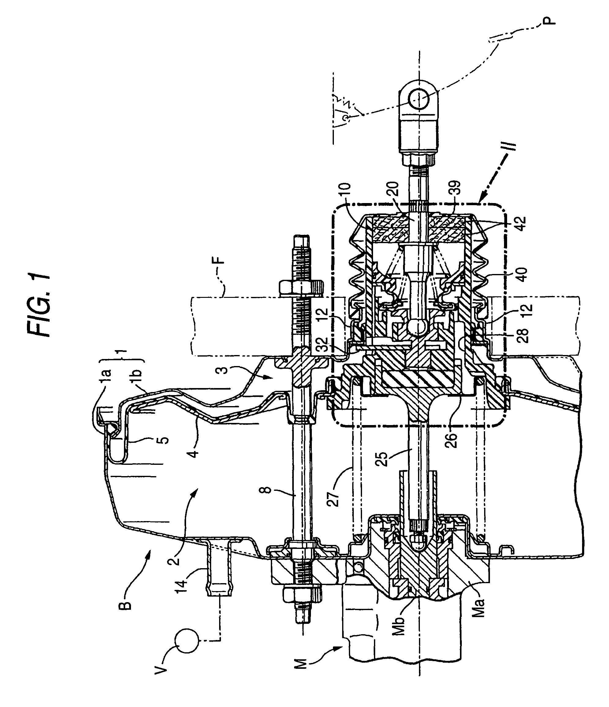
[0028]First of all, the explanation of the present invention will start here. In FIGS. 1 and 2, the booster shell 1 of the vacuum pressure booster B is composed of a pair of half shell bodies 1a, 1b, the opposed end portions of which are connected with each other. Both half shell bodies 1a, 1b are connected with each other by a plurality of tie rods 8 (Only one of them is shown in FIG. 1.) which penetrate them. The rear half shell body 1b is fixed to the front wall F of the vehicle chamber through the above tie rods 8, and the cylinder body Ma of the brake master cylinder M is fixed to the front half shell body 1a.

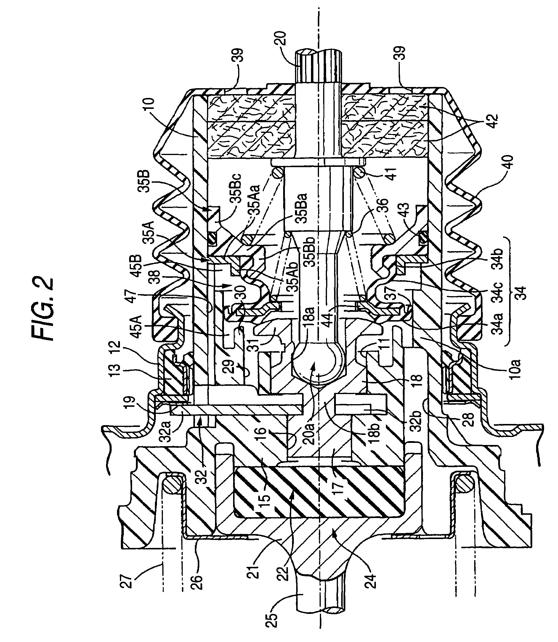
[0029]The inside of the booster shell 1 is partitioned into. the front side vacuum pressure chamber 2 and the rear side operation chamber 3 by the booster piston 4, which is accommodated in the booster shell 1 in such a manner that the booster piston 4 can be slid and reciprocated in the longitudinal direction, and also partitioned by the diaphragm 5 attached to the rear ...

second embodiment

[0061]Next, the present invention shown in FIG. 6 will be explained below.

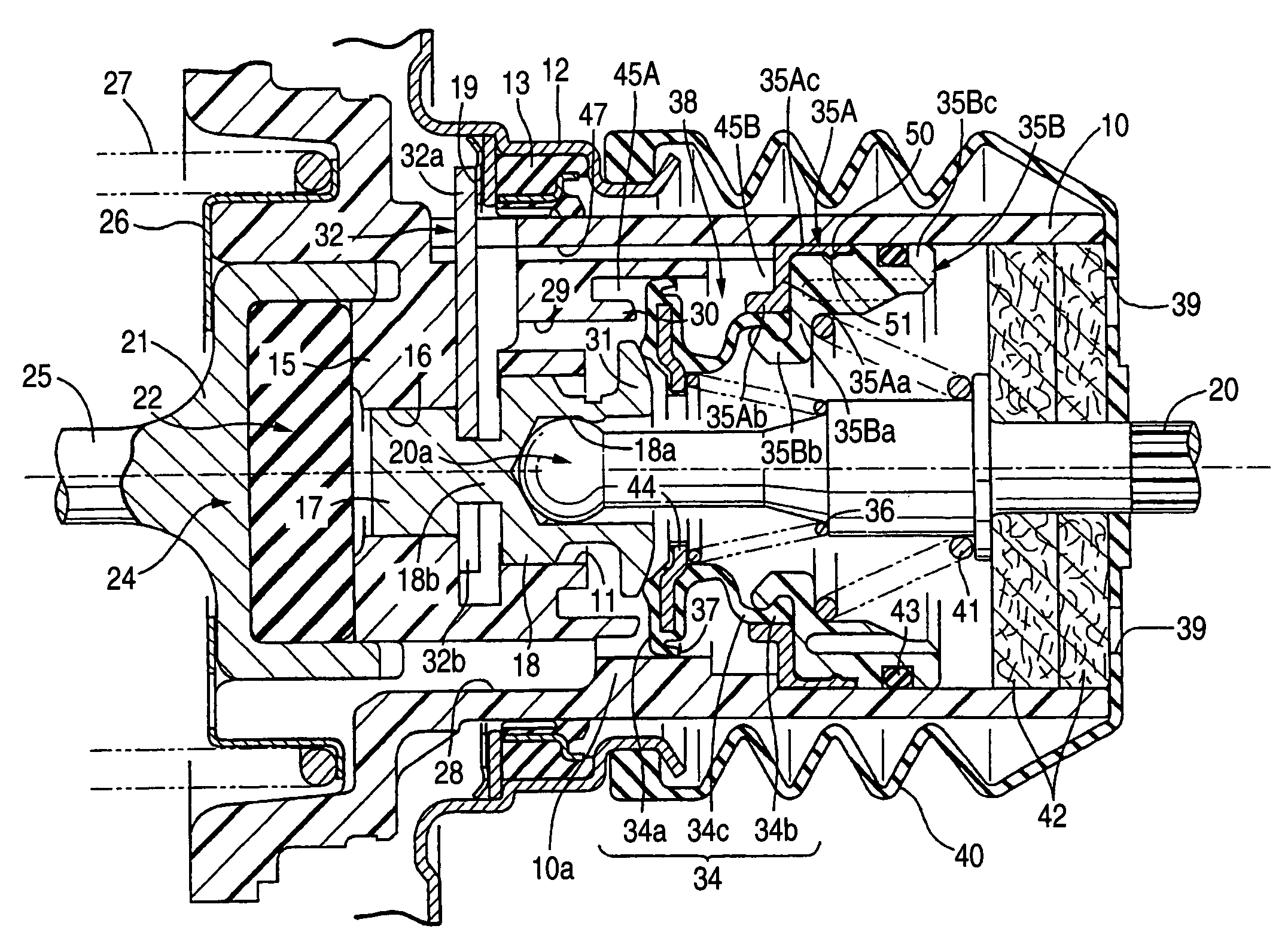
[0062]In this second embodiment, the cylindrical connecting portion 35Ac, which is engaged with the outer circumference of the front half portion of the engaging portion 35Bc of the rear valve holder 35B and also engaged with the inner circumferential face of the valve cylinder 10, is integrally connected with the flange portion 35Aa of the front valve holder 35A. The annular recess portion 50 and the annular protruding portion 51, which are elastically engaged with each other, are respectively formed in one and the other of the engaging faces of the connecting portion 35Ac and the engaging portion 35Bc. Except for the above points, the constitution of this second embodiment is substantially the same as the embodiment described before. Therefore, like reference characters are used to indicate like parts in FIG. 6, and the explanations are omitted here.

[0063]While the attaching bead portion 34b of the valve bod...


PUM


Abstract

A vacuum pressure booster has a booster shell; a booster piston; a valve cylinder including: a valve piston; an input rod; a control valve; and an input return spring, and the control valve including: an annular vacuum pressure introducing valve seat; an atmosphere introducing valve seat; a valve body including: an annular attaching bead portion; an expansion cylinder portion; and an annular valve portion; and a valve spring, wherein the attaching bead portion is tightly held by a pair of cylindrical holding portions formed in a pair of valve holders attached to the valve cylinder, and the diameter of the holding portion is smaller than the inner diameter of the valve cylinder.

Description

BACKGROUND OF THE INVENTION[0001]1. Field of the Invention[0002]The present invention relates to a vacuum pressure booster used for the boosting operation of a master cylinder of a brake of a vehicle. More particularly, the present invention relates to improvements in a vacuum pressure booster having: a booster shell; a booster piston accommodated inside the booster shall and partitioning the interior of the booster shell into a front side vacuum pressure chamber communicating with a vacuum pressure source and a rear side operation chamber; a valve cylinder communicating with the booster piston.[0003]The valve cylinder includes: a valve piston fitted into the valve cylinder to be slidable in a forward and rearward direction of the valve cylinder; an input rod coupling with the valve piston at a front end thereof; a control valve switching communication of the operation chamber with the vacuum pressure chamber and with air in accordance with a forward and rearward movement of the inp...

Claims


Application Information

Patent Timeline
IPC IPC(8): B60T8/44B60T13/57B60T13/575
CPCB60T13/57B60T13/575
Inventor YATABE, SHUUICHI
Owner AUTOLIV NISSIN BRAKE SYST JAPAN CO LTD
Why Eureka
Try Eureka