Semiconductor integrated circuit, pwm signal output device, and power conversion control apparatus

Active Publication Date: 2009-03-12
RENESAS ELECTRONICS CORP
View PDF5 Cites 16 Cited by
  • Summary
  • Abstract
  • Description
  • Claims
  • Application Information

AI Technical Summary

Benefits of technology

[0025]As described above, by sectioning a processing performed by the hardware circuit and a processing performed according to a software processing from each other, versatility of the semiconductor integrated circuit is maintained a

Problems solved by technology

However, influence of dead time causes mismatch of an output voltage of the power converter with a voltage command value and distortion in a load current waveform.
The system where compensation of a preset correction

Method used


Image

  • Semiconductor integrated circuit, pwm signal output device, and power conversion control apparatus
  • Semiconductor integrated circuit, pwm signal output device, and power conversion control apparatus
  • Semiconductor integrated circuit, pwm signal output device, and power conversion control apparatus

Examples


Example

First Embodiment

[0044]In a present embodiment, an example such that, in setting of a PWM timer where a conduction ratio of an upper arm side of a PWM signal increases as a PWM setting time decreases, “Hi” level of an output voltage pulse signal is an ON period of the upper arm side and the “Hi” levels are counted is shown. This is called a first case.

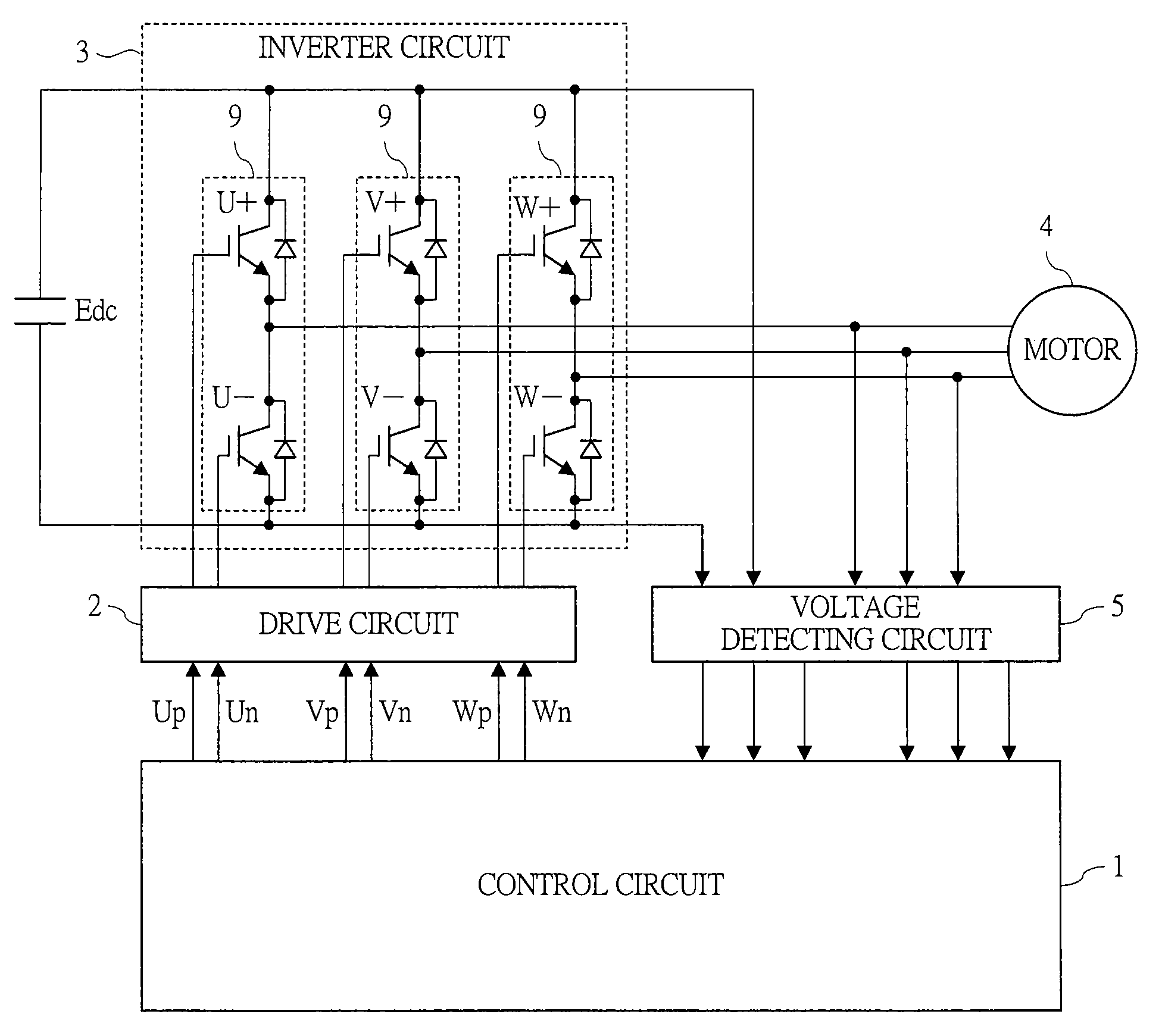
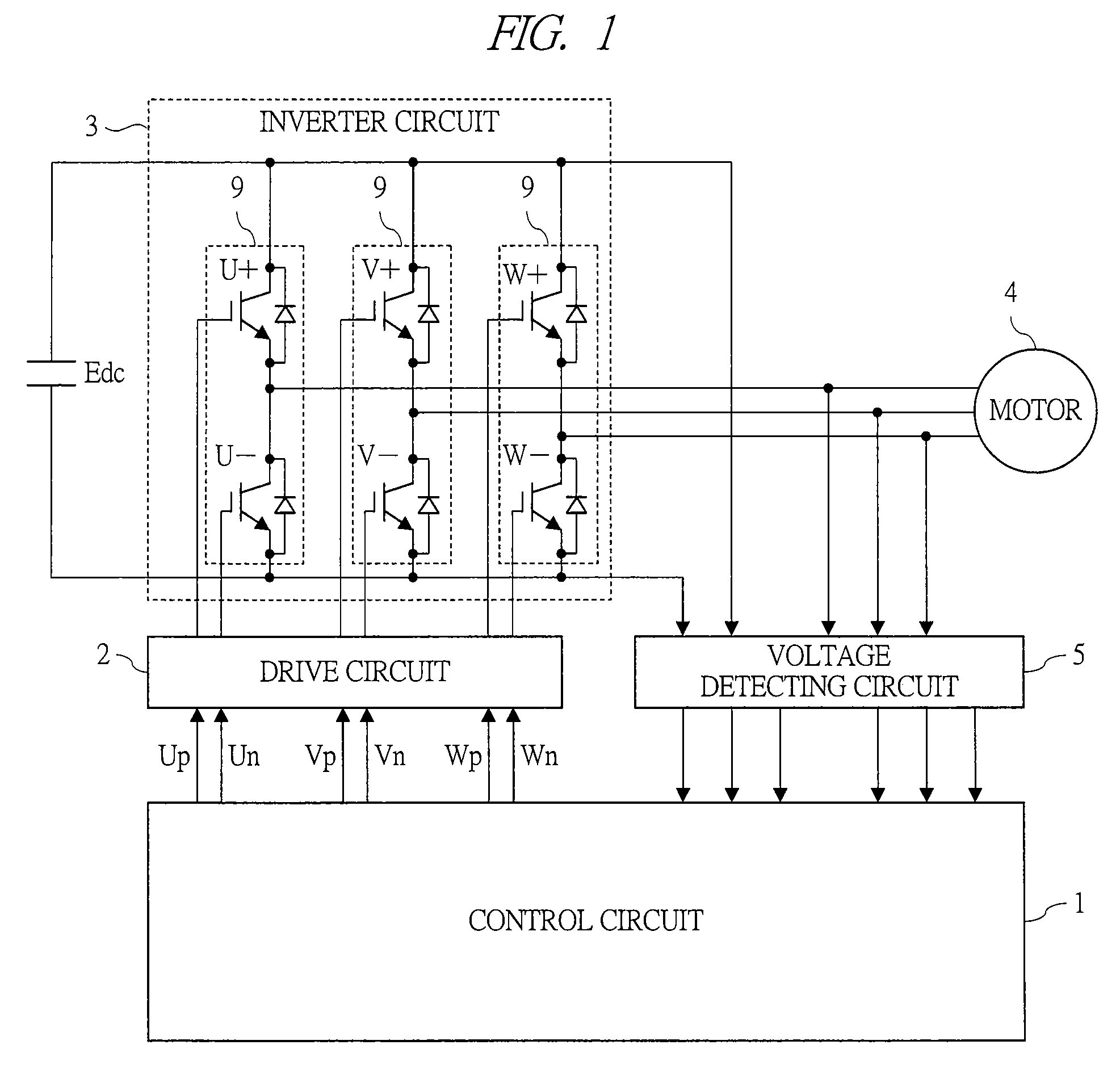
[0045]First, a first embodiment of a power conversion control apparatus according to the present invention will be described. FIG. 1 is an overall configuration diagram of a motor drive apparatus which is the power conversion control apparatus. The motor drive apparatus (power conversion control apparatus) according to the first embodiment comprises: a control circuit (PWM signal output device) 1 using a microcomputer (semiconductor integrated circuit); a drive circuit 2 which amplifies a PWM signal outputted from the control circuit 1 to drive switching circuits 9 in an inverter circuit 3 described later; the inverter circuit (power co...

Example

[0114]Regarding a second embodiment of the power conversion control apparatus (motor driving apparatus) according to the present invention, variation measurement and failure diagnosis of switching speeds at respective phases will be described with reference to FIGS. 9 and 10.

[0115]In the present embodiment, in a setting of a PWM timer where a conduction ratio of a PWM signal on an upper arm side increases as a PWM setting time is decreased, when “Hi” level of the output voltage pulse signal is ON period on the upper arm side and the “Hi” level is counted, time data set in a PWM setting time register corresponds to an ON time on the upper arm side of the PWM and an output voltage pulse signal counter value counts the ON time on the upper arm side of the PWM. A loading timing of a counter value into the register is set to both cycles of top and trough of a PWM carrier.

[0116]FIG. 9 is a schematic flowchart of a variation measuring method of a switching speed.

[0117]At a step (A), a thre...


PUM


Abstract

Provided is a control technique of a PWM conversion type power converter capable of compensating for a voltage error due to voltage drop mainly at a switching element and managing a switching time of a PWM signal at the same time, and capable of suppressing increase/decrease of software operation load and addition of a hardware circuit to the minimum. A semiconductor integrated circuit having a PWM signal generating unit which generates a PWM signal is provided with a PWM timer unit including a counter counting a pulse width of a pulse signal inputted from the outside with delay from a PWM signal, a register loading a counter value of the counter in synchronization with the PWM signal, and an A/D converting unit converting an analog signal serving as a source signal of the pulse signal inputted from the outside to a digital signal.

Description

CROSS-REFERENCE TO RELATED APPLICATION[0001]The present application claims priority from Japanese Patent Application No. JP 2007-232721 filed on Sep. 7, 2007, the content of which is hereby incorporated by reference into this application.TECHNICAL FIELD OF THE INVENTION[0002]The present invention relates to a PWM signal generation technique of a power converter controlled by a pulse width modulation (PWM) signal. More particularly, the present invention relates to a technique effectively applied to a control apparatus of a PWM type power converter that compensates for an applied voltage error due to dead time and delay of a switching element, and the like.BACKGROUND OF THE INVENTION[0003]For example, in a PWM signal generation technique for a power converter, when a power converter is PWM-controlled, it is essential to add dead time to a PWM signal so as to prevent short-circuiting due to switching delay of a switching element connected in series between power sources. However, infl...

Claims


Application Information

Patent Timeline
IPC IPC(8): H03K12/00
CPCG06F1/025H03K7/08H02P27/08
Inventor SUZUKI, TAKAHIRONOTOHARA, YASUOENDO, TSUNEHIROMORI, YUJI
Owner RENESAS ELECTRONICS CORP
Why Eureka
Try Eureka