Passive optical-based data center networks

a data center network and optical-based technology, applied in electromagnetic network arrangements, wavelength-division multiplex systems, electrical equipment, etc., can solve the problems of link oversubscription, inefficient load balancing, and power consumption of data centers

Active Publication Date: 2017-11-09
UNIV OF LEEDS
View PDF6 Cites 90 Cited by
  • Summary
  • Abstract
  • Description
  • Claims
  • Application Information

AI Technical Summary

Problems solved by technology

However, major concerns have recently been raised about the power consumption of data centers and its impact on global warming and on the electricity bill of data centers.
Given the steadily increasing number of servers and the exponentially growing traffic inside data centers, conventional data centers networking architectures suffer from performance limitations such as links oversubscription and inefficient load balancing.

Method used


Image

  • Passive optical-based data center networks
  • Passive optical-based data center networks
  • Passive optical-based data center networks

Examples


Embodiment Construction

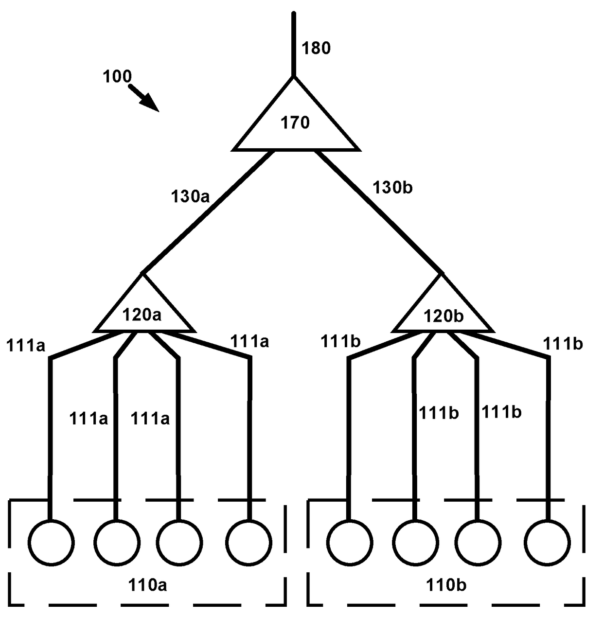
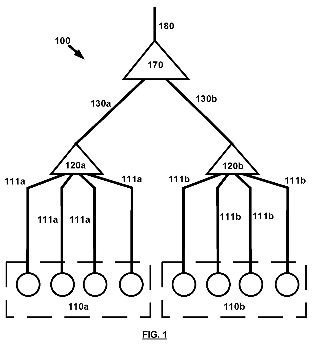
[0043]FIG. 1 shows a data center network according to some embodiments. The data center network 100 of FIG. 1 contains a first group of optical ports 110a for connection to respective servers of a first group of servers, a second group of optical ports 110b for connection to a second group of servers and a first lower passive optical routing element 120a.

[0044]The first lower passive optical routing element 120a is arranged to route optical communication signals between the first group of optical ports 110a and a first lower optical communication path 130a. A second lower passive optical routing element 120b is arranged to route optical communication signals between the second group of optical ports 110b and a second lower optical communication path 130b. An upper passive routing element 170 is arranged to:[0045]1. Route optical communication signals between the first lower optical communication path 130a and an upper optical communication path 180, and[0046]2. Route optical commun...


PUM


Abstract

A data centre network, comprises a first group of optical ports for connection to respective servers of a first group of servers; a second group of optical ports for connection to respective servers of a second group of servers; a first lower passive optical routing element arranged to route optical communication signals between the first group of optical ports and a first lower optical communication path; a second lower passive optical routing element arranged to route optical communication signals between the second group of optical ports and a second lower optical communication path; an upper passive optical routing element arranged to: (i) route optical communication signals between the first lower optical communication path and an upper optical communication path, and (ii) route optical communication signals between the second lower optical communication path and the upper optical communication path.

Description

[0001]Aspects of the invention relate to data centers and data center networks. In particular, embodiments relate to energy efficient data centres and data centre designs.BACKGROUND[0002]Recent years have witnessed an unprecedented growth in services and applications housed in modern data centers, such as web-search, scientific computations, social networks, file storage and distributed files systems. Today's data centers may host hundreds of thousands of servers, interconnected via switches, routers and high-speed links, making the choice of networking architecture within the data center of premium importance, as it impacts the data center scalability, cost, fault-tolerance, agility and power consumption.[0003]Significant research effort has been devoted over the last decade to design efficient data center networks. However, major concerns have recently been raised about the power consumption of data centers and its impact on global warming and on the electricity bill of data cente...

Claims


Application Information

Patent Timeline
Patent Type & Authority Applications(United States)
IPC IPC(8): H04B10/27H04J14/02
CPCH04J14/0267H04B10/27H04J14/0256H04J14/0282
Inventor ELMIRGHANI, JAAFAREL-GORASHI, TAISIRHAMMADI, ALI
Owner UNIV OF LEEDS
Why Eureka
Try Eureka