Automatic pouring machine and method for automtically pouring that have ability to pressurize

a technology of automatic pouring machine and automatic pouring method, which is applied in the direction of casting apparatus, molten metal supply equipment, manufacturing tools, etc., can solve the problems of long time-consuming and inefficient solidification time, difficult to achieve desired filling of molten metal, and low temperature on the surface of molten metal, etc., to achieve high fluidity, easy to use, and cheap and easy to obtain

Inactive Publication Date: 2017-11-16
SINTOKOGIO LTD +1
View PDF2 Cites 1 Cited by
  • Summary
  • Abstract
  • Description
  • Claims
  • Application Information

AI Technical Summary

Benefits of technology

This patent describes an automatic pouring machine that can efficiently pour molten metal into a mold and solidify it there. The machine uses a pressurized gas and granular material, such as dry silica sand, to squeeze the metal into the mold and plug it at the entrance. The machine also has the ability to move the mouth quickly and easily to connect with the mold's sprue. The use of dry silica sand makes the process easier and more user-friendly. Overall, the machine and method described in this patent improve the process of automatically pouring molten metal and ensure better quality and efficiency.

Problems solved by technology

Further, since the molten metal is confined there by means of pressurized gas, the time to solidify is long and inefficient.
However, depending on the arrangement of the cavities or the shapes of the runner and the sprue, heat is transferred to the filling material so that the temperature on the surface of the molten metal becomes low.
Thus, there are some cases where a desired filling of the molten metal is difficult.

Method used


Image

  • Automatic pouring machine and method for automtically pouring that have ability to pressurize
  • Automatic pouring machine and method for automtically pouring that have ability to pressurize
  • Automatic pouring machine and method for automtically pouring that have ability to pressurize

Examples


Embodiment Construction

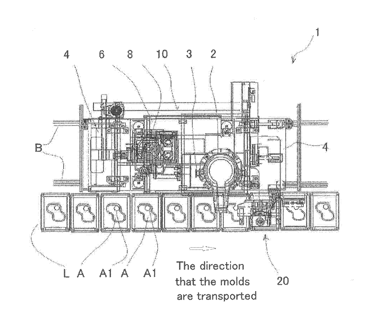
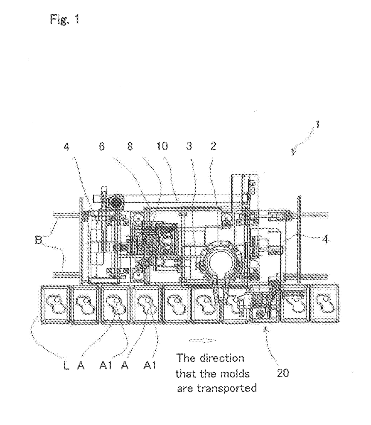
[0025]Below, an automatic pouring machine equipped with a unit for pressurizing the molten metal, which machine is an embodiment of the present invention, is discussed with reference to the drawings. FIG. 1 shows a plan view of the automatic pouring machine 1, which is an embodiment of the present invention. It is equipped with the unit 20 for pressurizing the molten metal. As in FIG. 1, the automatic pouring machine 1 is configured to move on a rail B that is disposed to be parallel to the line L of molds on which the molds are transported.

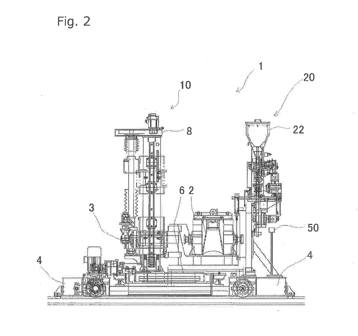
[0026]FIG. 2 is a front schematic view of the automatic pouring machine 1 as in FIG. 1. As in FIG. 2, a traversing carriage 4 is placed on the rail B so that it runs on it. The rail B is placed on the floor. A carriage for moving back and forth 6 is placed on the traversing carriage 4 so as to move perpendicularly to the rail B. Specifically, a rail (not shown) is placed on the upper plane of the traversing carriage 4 in the direction that is per...


PUM

PropertyMeasurementUnit
Timeaaaaaaaaaa

Abstract

To provide a machine and method for efficiently pouring and definitely filling only a desired cavity with molten metal to cause the molten metal to solidify there. The automatic pouring machine (1) that has an ability to pressurize having a ladle (2) for pouring molten metal into a mold (A) comprises a pouring unit (10) that can move a ladle in the direction parallel to, and in the direction perpendicular to, a line (L) of molds where a plurality of molds are transported and a unit (20) for pressurizing the molten metal that is supported by the pouring unit and that supplies pressurized gas and a granular material to the mold into which molten metal has been poured. The unit (20) supplies the pressurized gas and the granular material to the mold that is next to the mold into which the pouring unit pours molten metal.

Description

TECHNICAL FIELD[0001]The present invention relates to a pouring machine and a method for pouring that are used in a foundry. Specifically, it relates to a pouring machine and method that have the ability to pressurize molten metal in a mold.BACKGROUND ART[0002]In a foundry, molten metal that has melted in a melting furnace and that is at a high temperature is poured into a mold in an area for pouring, to thereby cast a product. When molten metal is poured into a mold, it is poured into the upper end of a pouring cup in consideration of shrinkage during solidification in the mold. After cooling the mold, the mold is shaken out. Then the sprue, the runner, and the riser, which are some of the parts other than the product, are separated from the product so as to be again melted, for return scrap. Among these parts, though the riser is needed during solidification to ensure the soundness of the product, the runner and the sprue are needed only for filling molten metal into a cavity duri...

Claims


Application Information

Patent Timeline
IPC IPC(8): B22D39/02B22D27/13B22D18/04
CPCB22D39/026B22D18/04B22D27/13B22D27/09B22D39/02
Inventor NISHIDA, TADASHIKATO, MASAYUKIBANNO, KOICHI
Owner SINTOKOGIO LTD
Why Eureka
Try Eureka