Method and Apparatus to Enhance Laminar Flow for Gas Turbine Engine Components

a gas turbine engine and laminar flow technology, applied in the direction of machines/engines, liquid fuel engines, lighting and heating apparatus, etc., can solve the problems of difficult to improve efficiency, adversely affect efficiency, and significant energy loss, and achieve the effect of enhancing laminar flow

Inactive Publication Date: 2017-11-16
RAYTHEON TECH CORP
View PDF13 Cites 3 Cited by
  • Summary
  • Abstract
  • Description
  • Claims
  • Application Information

AI Technical Summary

Benefits of technology

[0018]In another embodiment according to any of the previous embodiments, the gas turbine engine includes a compressor section, a combustor section downstream of the compressor section, and a turbine section downstream of the combustor section, and wherein the turbine section includes at least a high pressure turbine downstream of the combustor section and a low pressure turbine downstream of the high pressure turbine, and wherein the airfoil is located within the low pressure turbine.
[0019]In another featured embodiment, a method of enhancing laminar flow for a gas turbine engine component includes the steps of: a) positioning a component body within a flow path of a gas turbine engine, wherein the component body includes at least one internal cavity; b) directing a portion of the flow through at least one inlet opening formed in an outer surface of the component body and into the at least one internal cavity; c) expelling the flow from the at least one internal cavity via at least one outlet from the component body; and d) locating the at least one outlet opening at a lower pressure area in the internal cavity than the at least one inlet opening such that flow is drawn into the internal cavity from the at least one inlet opening and expelled out the at least one outlet.

Problems solved by technology

As hot engine gases flow around airfoils in the turbine section, turbulent flow can be generated along an external surface of the airfoils, which adversely affects efficiencies.
Airfoil friction drag is created by a combination of friction loss and mixing loss.
Friction loss from near-wall turbulence that impacts a boundary layer along the external surface of the airfoil can result in a significant energy loss.
In an uncooled airfoil configuration, such features are not available making it difficult to improve efficiency.

Method used


Image

  • Method and Apparatus to Enhance Laminar Flow for Gas Turbine Engine Components
  • Method and Apparatus to Enhance Laminar Flow for Gas Turbine Engine Components
  • Method and Apparatus to Enhance Laminar Flow for Gas Turbine Engine Components

Examples


Embodiment Construction

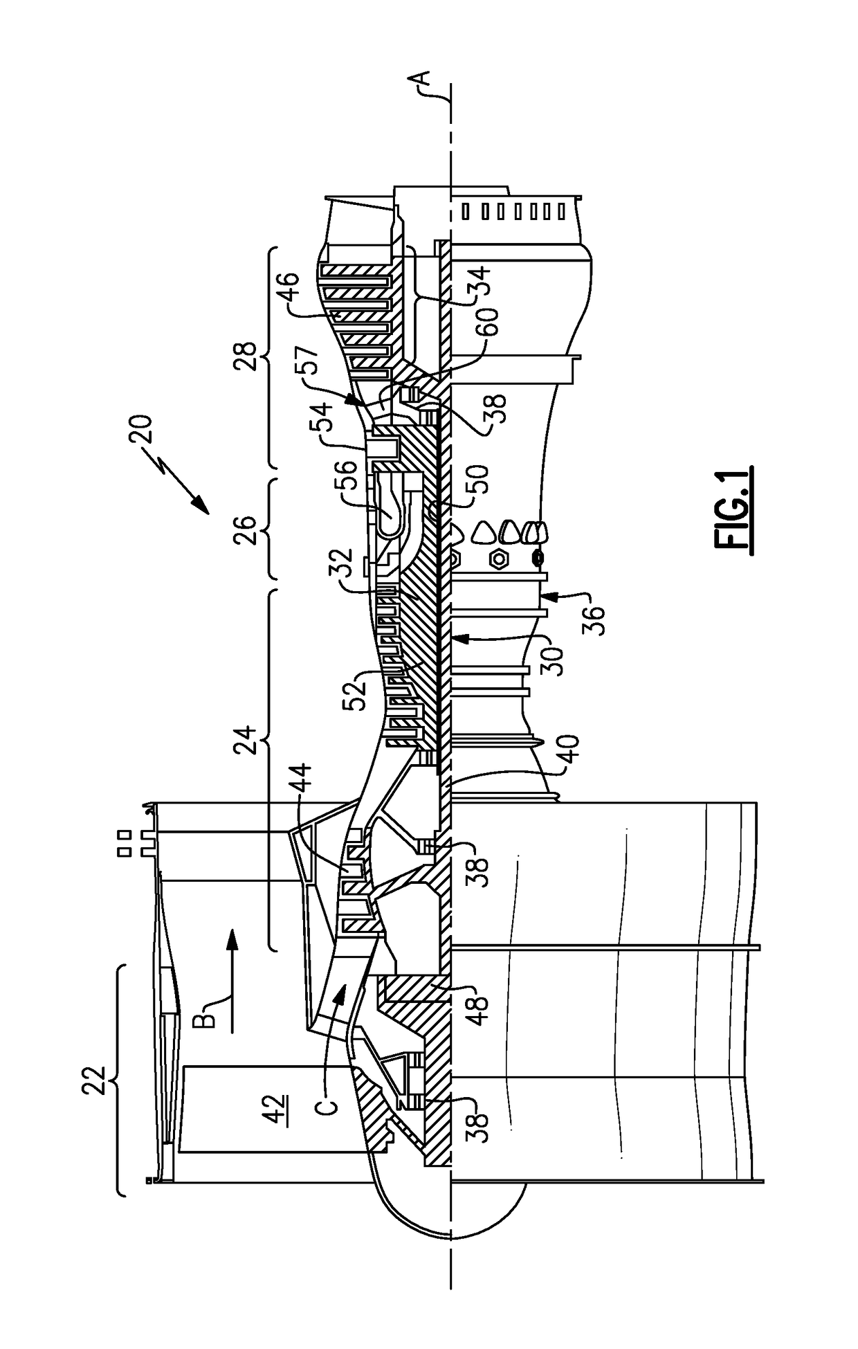
[0032]FIG. 1 schematically illustrates a gas turbine engine 20. The gas turbine engine 20 is disclosed herein as a two-spool turbofan that generally incorporates a fan section 22, a compressor section 24, a combustor section 26 and a turbine section 28. Alternative engines might include an augmentor section (not shown) among other systems or features. The fan section 22 drives air along a bypass flow path B in a bypass duct defined within a nacelle 15, while the compressor section 24 drives air along a core flow path C for compression and communication into the combustor section 26 then expansion through the turbine section 28. Although depicted as a two-spool turbofan gas turbine engine in the disclosed non-limiting embodiment, it should be understood that the concepts described herein are not limited to use with two-spool turbofans as the teachings may be applied to other types of turbine engines including three-spool architectures.

[0033]The exemplary engine 20 generally includes ...


PUM


Abstract

A gas turbine engine component has a component body configured to be positioned within a flow path of a gas turbine engine, wherein the component body includes at least one internal cavity. At least one inlet opening is formed in an outer surface of the component body to direct flow into the at least one internal cavity. At least one outlet from the internal cavity, wherein the at least one outlet is located at a lower pressure area in the internal cavity than the at least one inlet opening such that flow is drawn into the internal cavity from the at least one inlet opening and expelled out the at least one outlet. A gas turbine engine and a method of enhancing laminar flow for a gas turbine engine component are also disclosed.

Description

BACKGROUND OF THE INVENTION[0001]Gas turbine engines are continually being driven to provide higher thrust efficiencies to maximize performance. As hot engine gases flow around airfoils in the turbine section, turbulent flow can be generated along an external surface of the airfoils, which adversely affects efficiencies. One proven method to improve efficiency includes optimizing airfoil / endwall shapes and minimizing turbine cooling air usage to reduce friction and pressure drag around the airfoil.[0002]Airfoil friction drag is created by a combination of friction loss and mixing loss. Friction loss from near-wall turbulence that impacts a boundary layer along the external surface of the airfoil can result in a significant energy loss. In a cooled airfoil configuration, film cooling air may be targeted towards different areas or via different shaped holes to lessen the impact on friction and mixing loss factors. In an uncooled airfoil configuration, such features are not available m...

Claims


Application Information

Patent Timeline
Patent Type & Authority Applications(United States)
IPC IPC(8): F01D5/14F04D29/32F02C3/04F01D9/02F04D29/54F01D9/04
CPCF01D5/147F02C3/04F01D9/041F01D9/023F04D29/542F04D29/324F05D2220/32F05D2240/80F05D2240/35F01D5/14F01D5/141F01D5/145F01D5/18F01D5/186Y02T50/60F23R3/002F23R3/04
Inventor AUXIER, JAMES TILSLEY
Owner RAYTHEON TECH CORP
Why Eureka
Try Eureka