Low erosion fluid conduit with sharp section geometry

a fluid conduit and geometry technology, applied in the direction of bends, pipe protection, pipe protection, etc., can solve the problems of main sources of erosion-related failures, eroding of pipe elbows of any angle, and easy erosion of fluid conduits having circular flow passages, etc., to reduce erosion, increase component life span, and flow speed up the effect of speed

Active Publication Date: 2021-05-11
FMC TECH INC
View PDF26 Cites 0 Cited by
  • Summary
  • Abstract
  • Description
  • Claims
  • Application Information

AI Technical Summary

Benefits of technology

[0015]Thus, the fluid conduit of the present disclosure provides an optimized flow passage geometry which significantly reduces erosion and increases component life span without the use of erosion protective coatings, baffles or deflectors. The cross sectional geometry of the flow passage allows for higher flow speeds with particle-contaminated fluids without significant erosion effects. In addition, the cross sectional configuration of the flow passage results in a greater laminar flow regime, less disturbed flow (i.e., low turbulence kinetic energy (TKE)), which is beneficial for downstream flow separation, and notable heat retention, thus requiring less insulation of the flow conduit.
[0016]Fluid conduits in the form of pipe bends with triangular flow passages in particular allow for high flows of highly contaminated fluids with significantly less erosive wear. Thus, this geometry can help solve current wear issues found in elbows which are used in hydrocarbon fracking and transport applications. The geometry can also reduce failures of elbows used for slurry type flows found in the mining industry. Such benefits are achieved without the use of baffles, vanes, deflectors or material coatings, which are typically used to reduce erosion in elbows having circular flow passages.

Problems solved by technology

However, fluid conduits having circular flow passages are susceptible to erosion, especially when used to convey fluids at high velocities and / or containing abrasive particles.
The problem with erosion in fluid conduits having circular flow passages is particularly prevalent in pipe bends, such as pipe elbows.
Pipe elbows of any angle are notorious for eroding in the presence of high velocity fluids containing abrasive particles such as sand, slurries or any other particles which are generated from upstream wear in the piping system or are introduced into the piping system in applications such as fracking, mining and coal and hydrocarbon transport.
Pipe elbows are one of the main sources of erosion-related failures in fracking and hydrocarbon transport.
Although these solutions help to reduce erosion, they are limited and short term.
In addition, they reduce the flow area of the elbow, thus sacrificing elbow size and performance for less erosion.

Method used


Image

  • Low erosion fluid conduit with sharp section geometry
  • Low erosion fluid conduit with sharp section geometry
  • Low erosion fluid conduit with sharp section geometry

Examples


Embodiment Construction

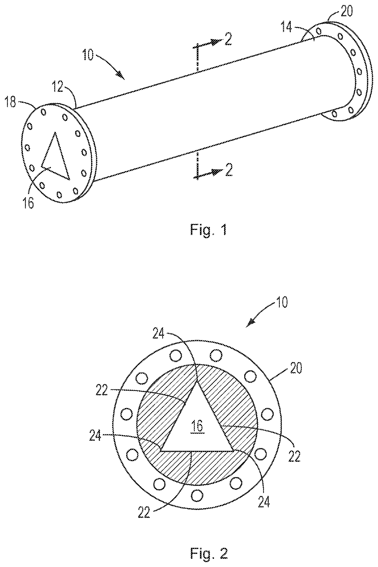
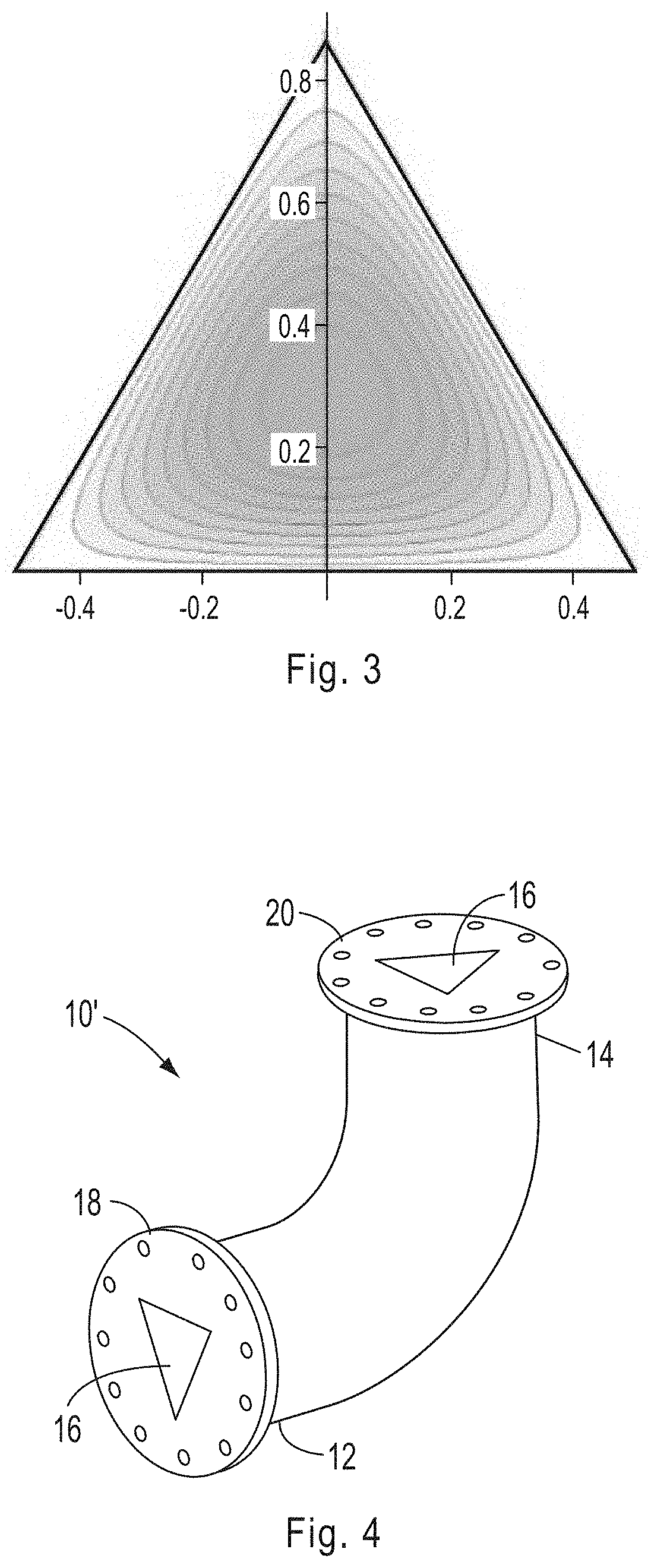
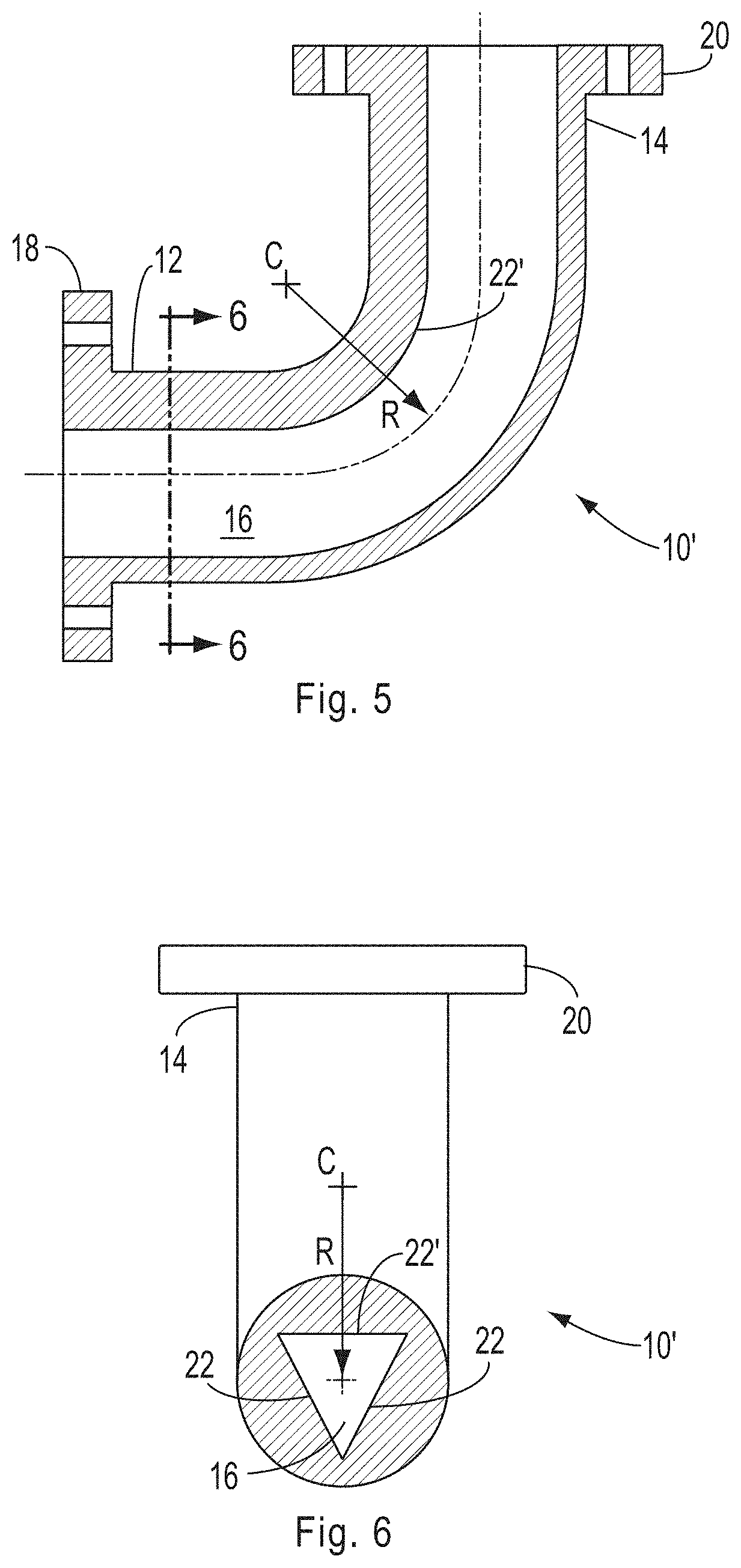
[0039]The present disclosure is directed to a fluid conduit having a longitudinal flow passage, at least a portion of which comprises a transverse cross section that is configured as a polygon, such as a convex polygon or a concave polygon. The fluid conduit may comprise any component through which a fluid is intended to flow. Examples of fluid conduits to which the present disclosure is applicable include, but are not limited to, pipes, pipe segments, pipe fittings (such as pipe bends, elbows and joints), pup joints, flowlines, flow loops, flowline jumpers, pipelines, manifolds, hydrocarbon production system components, fluid meters and flow control devices, such as flow control valves.

[0040]The portion of the flow passage which comprises the polygonal cross section may define the entire flow passage through the fluid conduit or only a portion of the flow passage. For example, a fluid conduit in accordance with the present disclosure may comprise a flow passage having a first end p...


PUM


Abstract

A fluid conduit has a longitudinal flow passage which includes a transverse cross section that is configured as a polygon, such as a convex or a concave polygon.

Description

FIELD OF THE DISCLOSURE[0001]The present disclosure is directed to fluid conduits. More particularly, the disclosure is directed to a fluid conduit having a flow passage which comprises a cross section that is configured as a polygon, for example a convex polygon or a concave polygon.BACKGROUND OF THE DISCLOSURE[0002]Prior art flow conduits typically comprise flow passages having circular cross sections. Such conduits are relatively simple to manufacture and are sufficiently strong for most applications. However, fluid conduits having circular flow passages are susceptible to erosion, especially when used to convey fluids at high velocities and / or containing abrasive particles.[0003]The problem with erosion in fluid conduits having circular flow passages is particularly prevalent in pipe bends, such as pipe elbows. Pipe elbows of any angle are notorious for eroding in the presence of high velocity fluids containing abrasive particles such as sand, slurries or any other particles whi...

Claims


Application Information

Patent Timeline
Patent Type & Authority Patents(United States)
IPC IPC(8): F16L9/00F16L43/00F16L57/06
CPCF16L9/006F16L43/00F16L57/06F16L9/20
Inventor SILVA, GABRIEL
Owner FMC TECH INC
Why Eureka
Try Eureka