
Furniture system having a linear actuator

Active Publication Date: 2017-11-16
LOGICDATA ELECTRONICS & SOFTWARE ENTWICKLUNGS
View PDF6 Cites 6 Cited by
  • Summary
  • Abstract
  • Description
  • Claims
  • Application Information

AI Technical Summary

Benefits of technology

The present disclosure relates to an improved furniture system with a linear actuator that reduces noise generation and provides flexibility in use. The improvement is based on the use of a friction gear mechanism or a gear mechanism with a friction gear stage that eliminates noise caused by teeth meshing. The linear actuator includes a motor, an adjustment member, and a gear mechanism, and the design allows for a coaxial construction and high flexibility. The system also includes planetary elements with cylindrical sleeves and friction pads for pinching and synchronization of multiple actuators. Additionally, a position sensor can be used to reduce or eliminate the impact of gear slip on the determination of the adjustment member position.

Problems solved by technology

The gear mechanism may represent a main source of noise development.
Noises in gear mechanisms, e.g. in toothed gear mechanisms, can result from production-related imprecisions, which may result in meshing errors, which in turn can induce vibration.
To some extent, this problem can be reduced by gear components that are produced in a very precise manner, which however may considerably increase production costs of the linear actuator.
Linear actuators of the first configuration can generally have of low noise level due to the design of the meshing in the worm gear mechanism or helical gear mechanism, but the angular arrangement comes with considerable disadvantages, in terms of product design, inter alia.
Nevertheless, noise generation, which can eventually be highly tolerance-dependent, is disadvantageous here.
Passive measures for noise reduction such as encapsulation of the gear mechanism may involve high spatial requirements and thermal problems.

Method used


Image

  • Furniture system having a linear actuator
  • Furniture system having a linear actuator
  • Furniture system having a linear actuator

Examples


Embodiment Construction

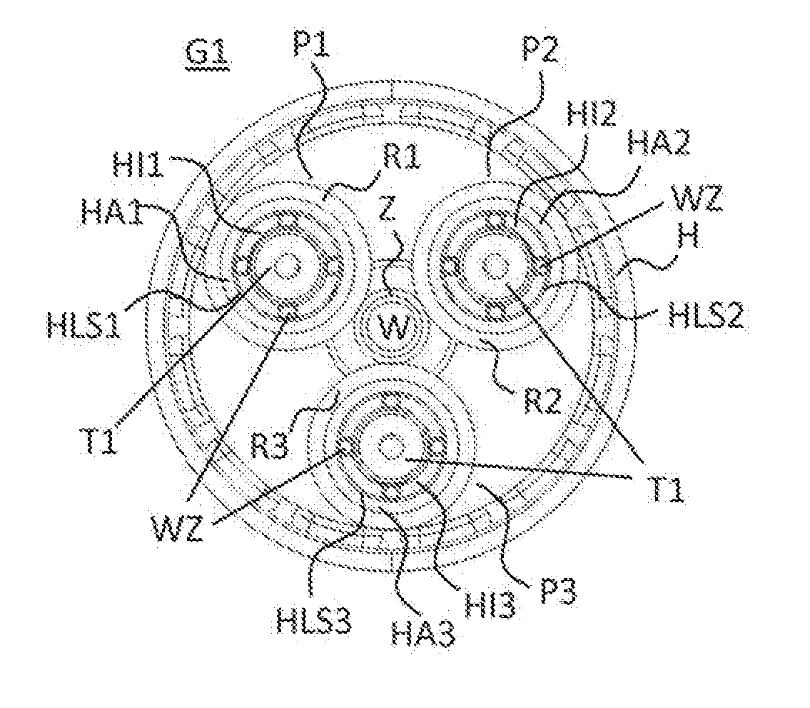
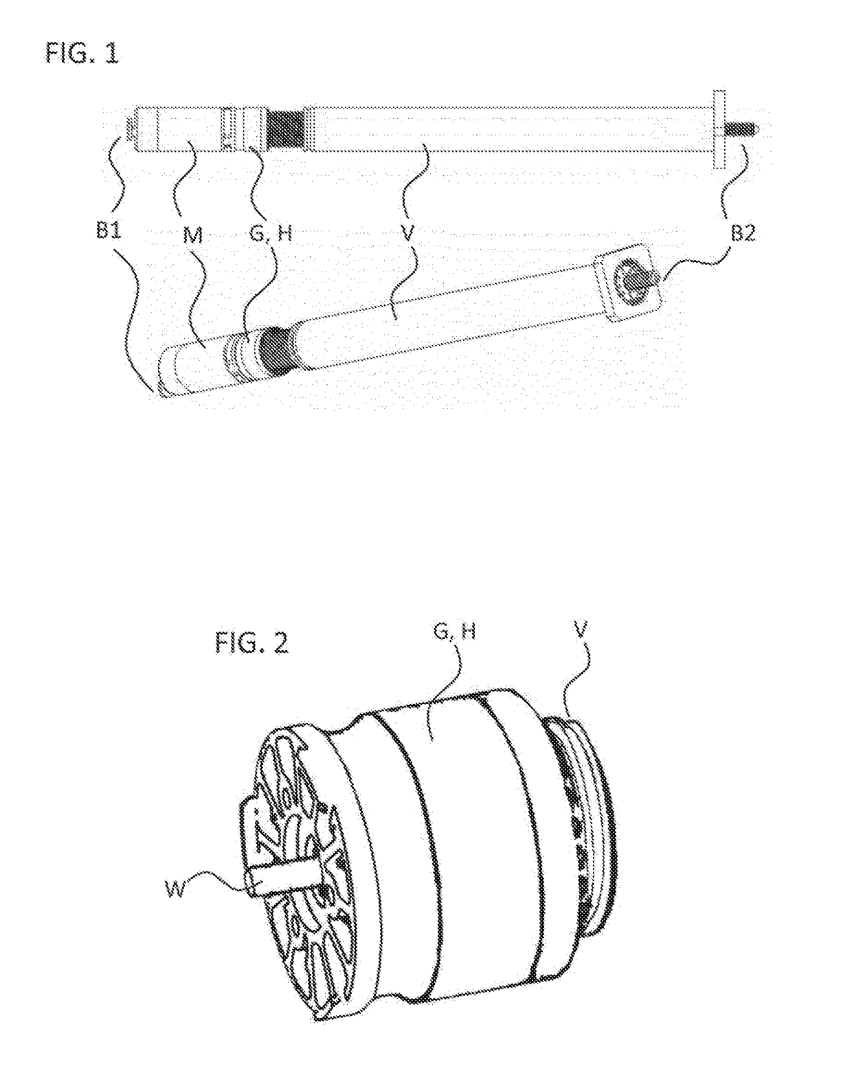
[0055]FIG. 1 shows an example of an embodiment of a linear actuator according to the improved concept. The upper part of FIG. 1 shows a side view of the linear actuator, whereas the lower part of FIG. 1 shows a perspective view of this linear actuator.

[0056]The linear actuator includes a gear mechanism G, a motor M, which is coupled to the gear mechanism G on the drive side, as well as an adjustment member V connected to the gear mechanism G on the output side. The linear actuator further comprises a first fastening element B1 fixed to the motor M and a second fastening member B2 fixed to the adjustment member V.

[0057]The adjustment member V includes a telescopic spindle. Exemplary embodiments of the adjustment member V are shown in documents DE 10 2012 102 298 A1 as well as DE 10 2012 013 979 A1, the disclosures of which are incorporated in their entirety into the present document by reference.

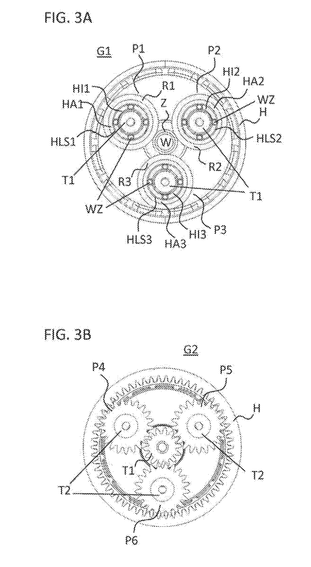
[0058]In the illustrated embodiment of the linear actuator, the gear mechanism G includes...


PUM


Abstract

A furniture system having a furniture item which includes an electrically-adjustable component, a control unit and a linear actuator for adjusting a component of the furniture item is provided. The linear actuator includes a gear mechanism including a hollow element and a first stage formed as a friction wheel stage. The linear actuator further includes a motor on a drive side and an adjustment member arranged on an output side. The linear actuator, in particular the motor, the gear mechanism and the adjustment member are adapted to alter a length of the adjustment member by means of the motor and the gear mechanism. The control unit is coupled with the linear actuator and adapted to actuate the linear actuator for adjusting the component.

Description

BACKGROUND OF THE INVENTION[0001]The present disclosure relates to a furniture system having a linear actuator for adjusting a component of a furniture item, e.g. for adjusting the height of a table or for adjusting the height or the position of a component of a lounging furniture item or a seating furniture item.[0002]Linear actuators conventionally serve for adjusting two parts which are moveable relative to one another. Linear actuators are used in height-adjustable tables for lifting or lowering a table top on a rack of a table, for example. Typically, linear actuators include an electric motor, a gear mechanism and an adjustment member such as a spindle, for example. Besides the performance of the linear actuator, reliability and required construction space, the noise level of the linear actuators can be an essential quality criteria. The gear mechanism may represent a main source of noise development.[0003]Noises in gear mechanisms, e.g. in toothed gear mechanisms, can result ...

Claims


Application Information

Patent Timeline
IPC IPC(8): F16H25/20F16H13/06F16H37/02F16H57/00A47B9/04A47B9/20A47C1/02A47C17/04
CPCF16H25/2003F16H57/0006F16H37/02F16H13/06A47B9/20A47B9/04A47B2009/046A47C17/04A47C1/02F16H2025/2087F16H25/20F16H13/02
Inventor KOLLREIDER, DANIEL
Owner LOGICDATA ELECTRONICS & SOFTWARE ENTWICKLUNGS
Learn More