
Fishing lure blade body attractor apparatus and methods thereof

a technology of lure body and attractors, which is applied in the field of fishing lure body attractors, can solve the problems of creating vibrations and none of the examples or prior art discloses, and achieve the effects of less noise, increased distance of protruding sides, and greater time between contacts

Active Publication Date: 2019-01-31
SCHWARTZ JASON K
View PDF24 Cites 4 Cited by
  • Summary
  • Abstract
  • Description
  • Claims
  • Application Information

AI Technical Summary

Benefits of technology

The invention is a new blade design for a fishing lure that allows the blade to move and make noise as it passes through water. The blade has fixed protruding sides, but an aperture or hole in between them allows it to be attached to a jig body using a split ring or equivalent. This attachment distance can be adjusted by the user to control the speed and noise generated as the fishing lure moves through the water. The blade can also have variable gaps that adjust the distance between the blade and the jig body, allowing for less noise or more frequent contact. Overall, this design improves the realism and noise of fishing lures.

Problems solved by technology

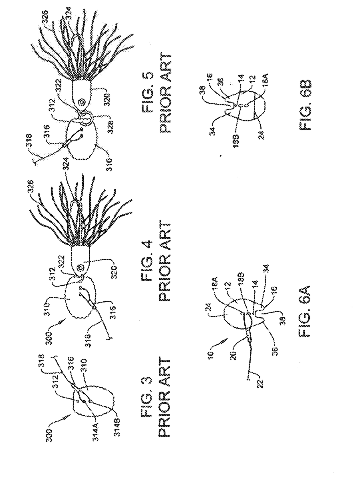
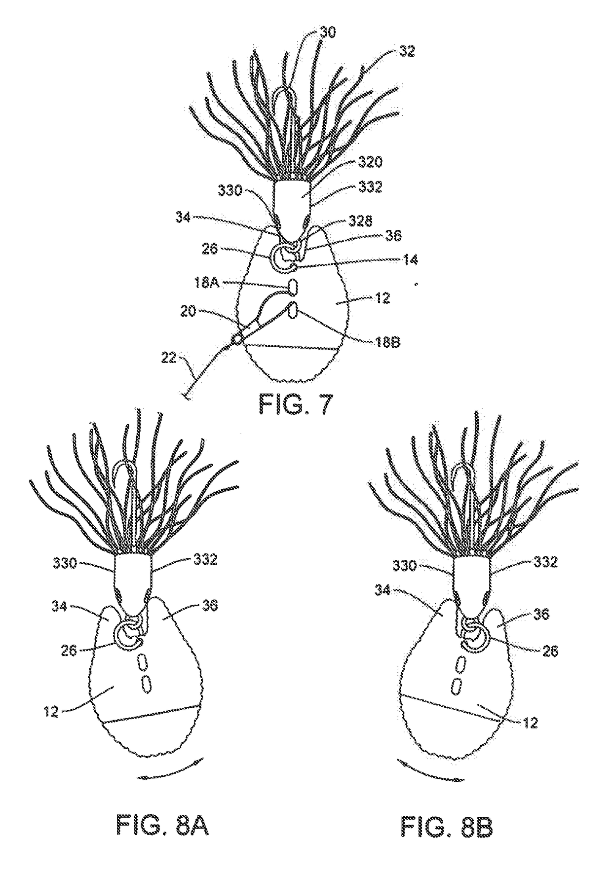
None of these examples provide a fishing lure configured with fixed (or variable) protruding sides to allow attachment of the blade body to a jig body by using an attachment device, such as a split ring or equivalent connected between the blade body and the eyelet of the jig body to keep the jig body a distance away from the blade body, and in which the blade body will swivel, oscillate or otherwise move from one end of the jig body to the other between the protruding sides and generate noise, reflect light and create vibrations as the jig body makes contact with the protruding sides of the blade, as the fishing lure is pulled through the water.
Further, none of the examples or prior art discloses a blade configuration as set forth above with a first side and a second side with a surface relief grating image effect component on at least one of the sides of the blade body, and possibly on both sides, functioning to reflect light in various directions, thereby further aiding in attracting fish to the lure, as the fishing lure is pulled through the water.

Method used


Image

  • Fishing lure blade body attractor apparatus and methods thereof
  • Fishing lure blade body attractor apparatus and methods thereof
  • Fishing lure blade body attractor apparatus and methods thereof

Examples


Embodiment Construction

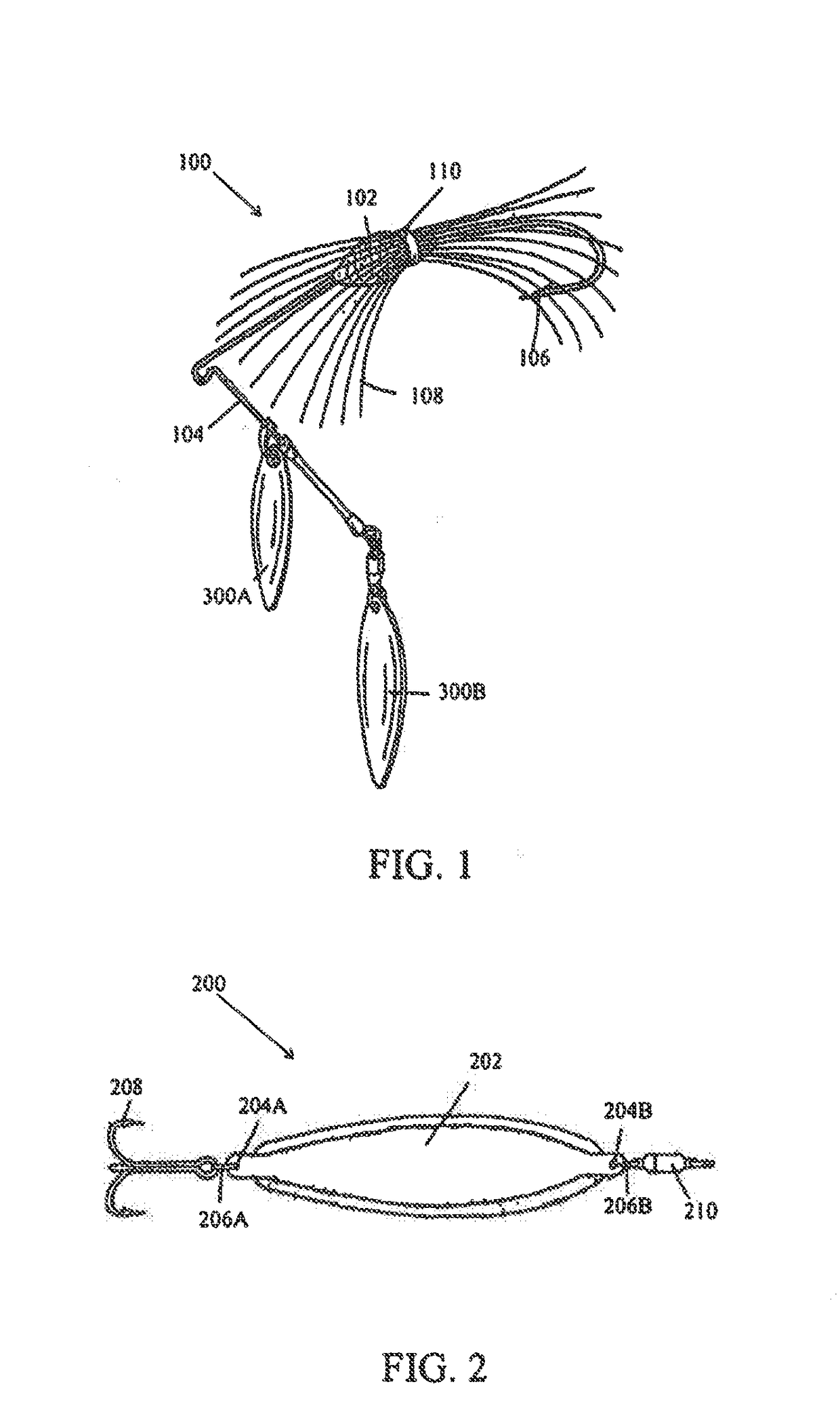
[0038]As mentioned herein, there are many types of fishing lures and attractors that include a blade body component. As an example, FIG. 1 illustrates one embodiment of a spinner-bait fishing lure that includes two blade bodies. More specifically, as shown in FIG. 1, the spinnerbait fishing lure 100 includes a base element 102 that interconnects to a wire 104 on one end and a hook 106 on the other end. A plurality of streamers (silicone or rubber skirt) 108 surround the base element 102 and are secured by a band (or collar) 110. As shown in FIG. 1, two blade body components 112A, 112B are assembled to the wire 104.

[0039]FIG. 2 illustrates another embodiment of a fishing lure using a blade, specifically a minnow spoon fishing lure. More specifically, as shown in FIG. 2, the minnow spoon fishing lure 200 includes a blade body 202 that includes two connection holes 204A, 204B. Rings 206A, 206B engage with connection holes 204A, 204B respectively. A hook 208 assembles to ring 206A and a...


PUM


Abstract

A blade body of a fishing lure comprises a first protruding side and a second protruding side, creating a gap, and a jig body connected to the blade body such that when the blade body and jig body are connected and pulled through water, the blade body moves in a side to side motion limited by contact between the jig body and the first and second protruding sides.

Description

[0001]The present application is a continuation of and claims priority to U.S. Provisional Patent Application Ser. No. 62 / 537,109, filed Jul. 26, 2017, and entitled “Fishing Lure Blade Body Attractor Apparatus”. The provisional patent application is hereby incorporated by reference in its entirety.FIELD OF INVENTION[0002]The present invention relates generally to fishing lure blade body attractors, and more particularly to fishing lures that include a blade body configured to be attached to a jig body with a split ring to create noise, light and vibrations that aid in attracting fish to the lure, as the fishing lure with the blade body is pulled through the water.[0003]The present invention contemplates a blade configuration that comprises fixed gapped protruding sides and which allows attachment of the blade to a jig body by using an attachment device, such as a split ring or equivalent connected between the blade and the eyelet of the jig body, to keep the jig body a predetermined...

Claims


Application Information

Patent Timeline
Patent Type & Authority Applications(United States)
IPC IPC(8): A01K85/14
CPCA01K85/14A01K85/18
Inventor SCHWARTZ, JASON K.
Owner SCHWARTZ JASON K
Learn More