Electromagnetic valve

a technology of electromagnetic valves and valve parts, applied in the field of electromagnetic valves, can solve the problems of increased noise generation and increased wear, and achieve the effect of improving the positive connection and simplifying the overall assembly of even a bistable valv

Inactive Publication Date: 2005-09-29
AWECO APPLIANCE SYST
View PDF11 Cites 1 Cited by
  • Summary
  • Abstract
  • Description
  • Claims
  • Application Information

AI Technical Summary

Benefits of technology

[0034] In one special embodiment, each pole piece is for this purpose provided with a corresponding cylindrical projection, onto which an annular magnet can be slipped. This provides for a radial fixation of the permanent magnets. Axial fixation can be initiated by appropriately designing the spacer element or its guide elements, thereby making the overall assembly of even a bistable valve particularly simple. In the described further development of the invention, only the pole pieces, valve body, guide piece, if necessary with integrated filter, and permanent magnets need be inserted into a cylindrical tube and fixed in place by attaching the pole pieces, e.g., by welding. The unit fabricated

Problems solved by technology

An eccentric collision by the valve body with the valve seat had previously been possible

Method used


Image

  • Electromagnetic valve
  • Electromagnetic valve
  • Electromagnetic valve

Examples


Embodiment Construction

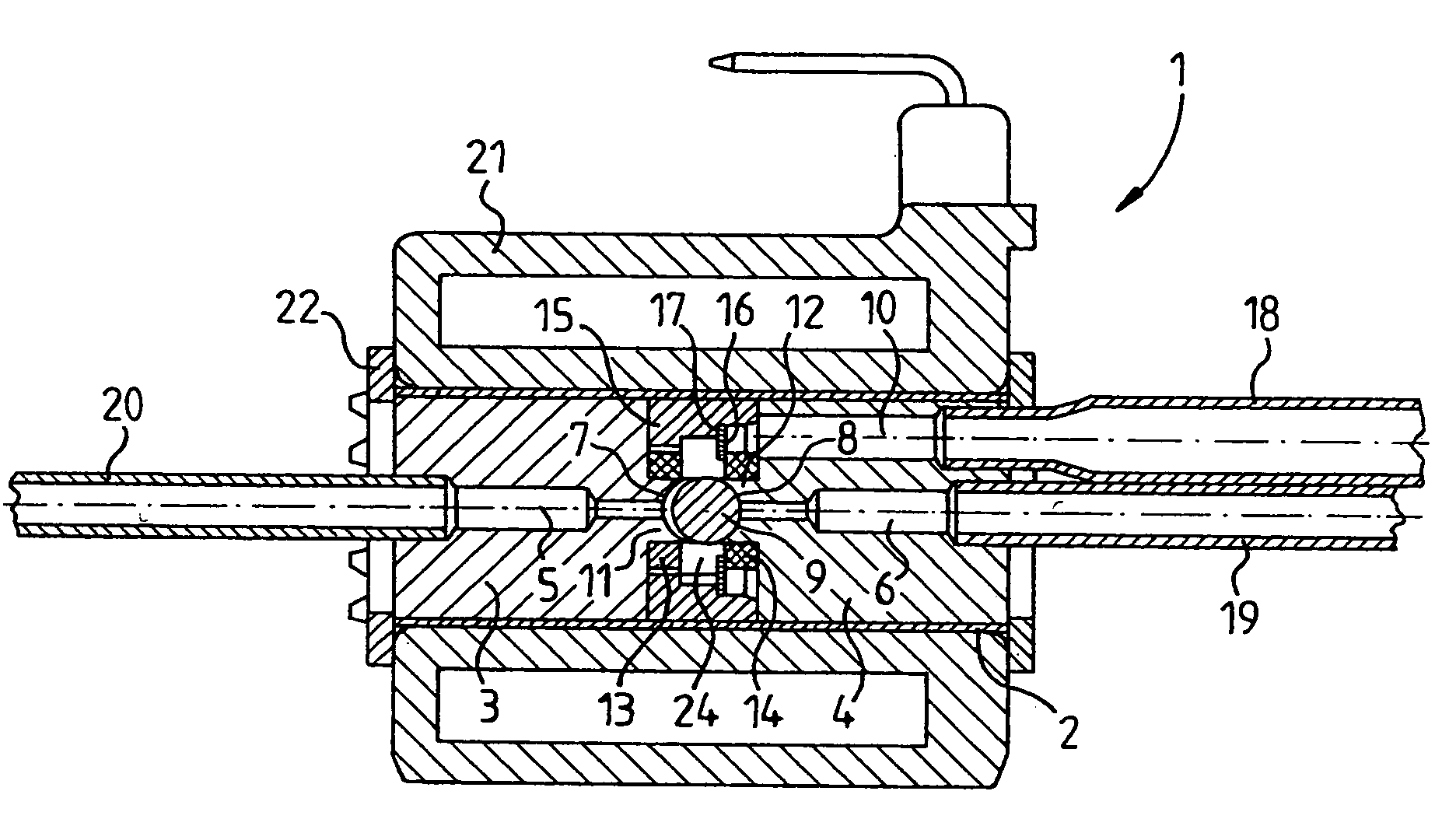
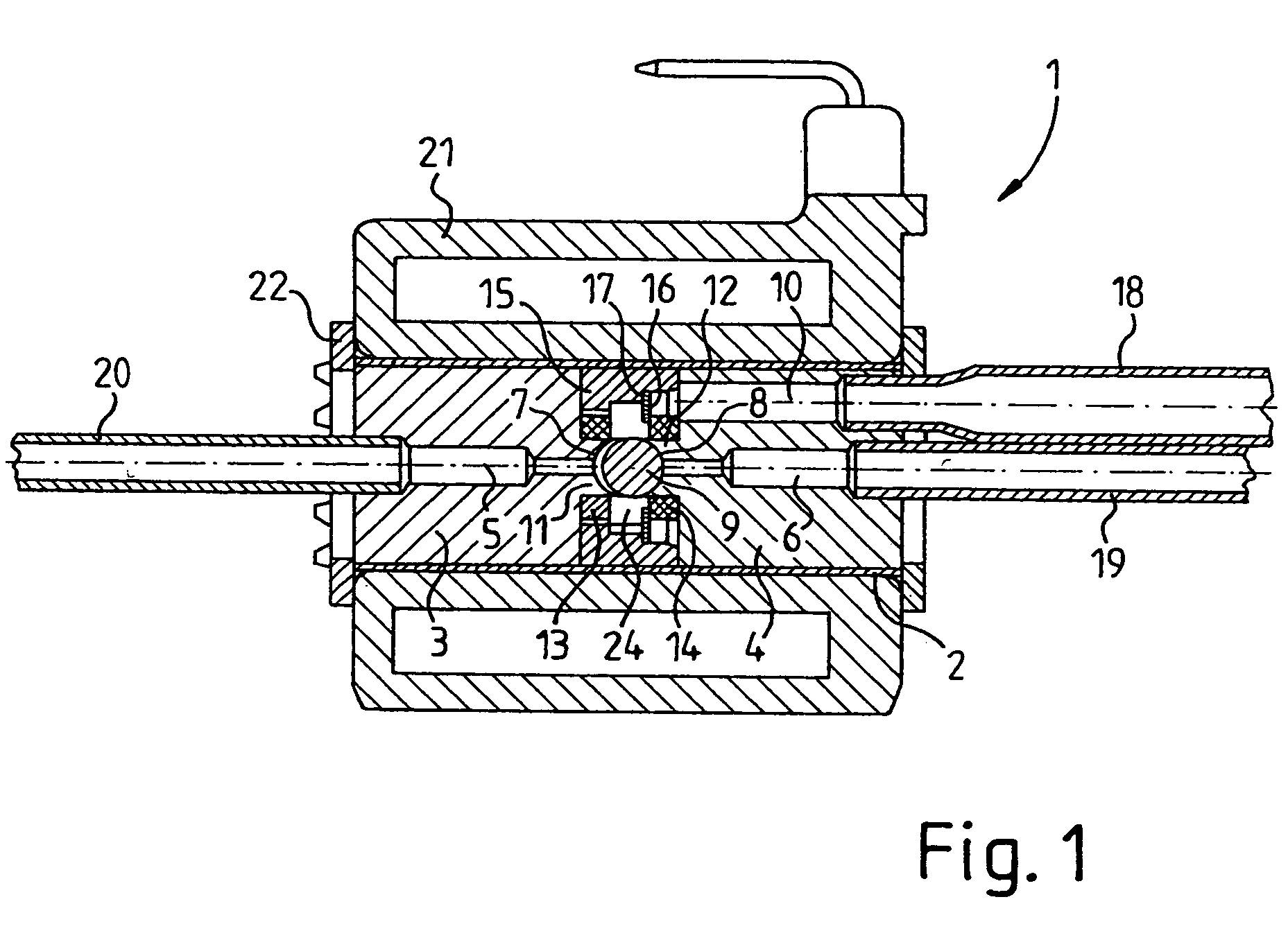
[0046] Valve 1 encompasses a valve housing 2 designed as a cylindrical tube, into which two pole pieces 3, 4 are inserted. A respective hole 5, 6, each serving as a fluid line, is introduced in pole pieces 3, 4. Fluid lines 5, 6 empty into two valve seats 7, 8, which are spherical, and hence tailored to the shape of a ball-shaped valve body 9. In the switching state shown, valve body 9 closes valve seat 8.

[0047] In addition to centric hole 6, pole piece 4 also accommodates another eccentric hole 10, which serves as an inlet for the fluid.

[0048] The two pole pieces 3, 4 are provided with cylindrical projections 11, 12 in the form of cross sectionally tapered segments, upon which the two annular magnets 13, 14 are placed. Annular magnets 13, 14 establish a roughly flush seal with pole pieces 3,4 or valve seats 7, 8.

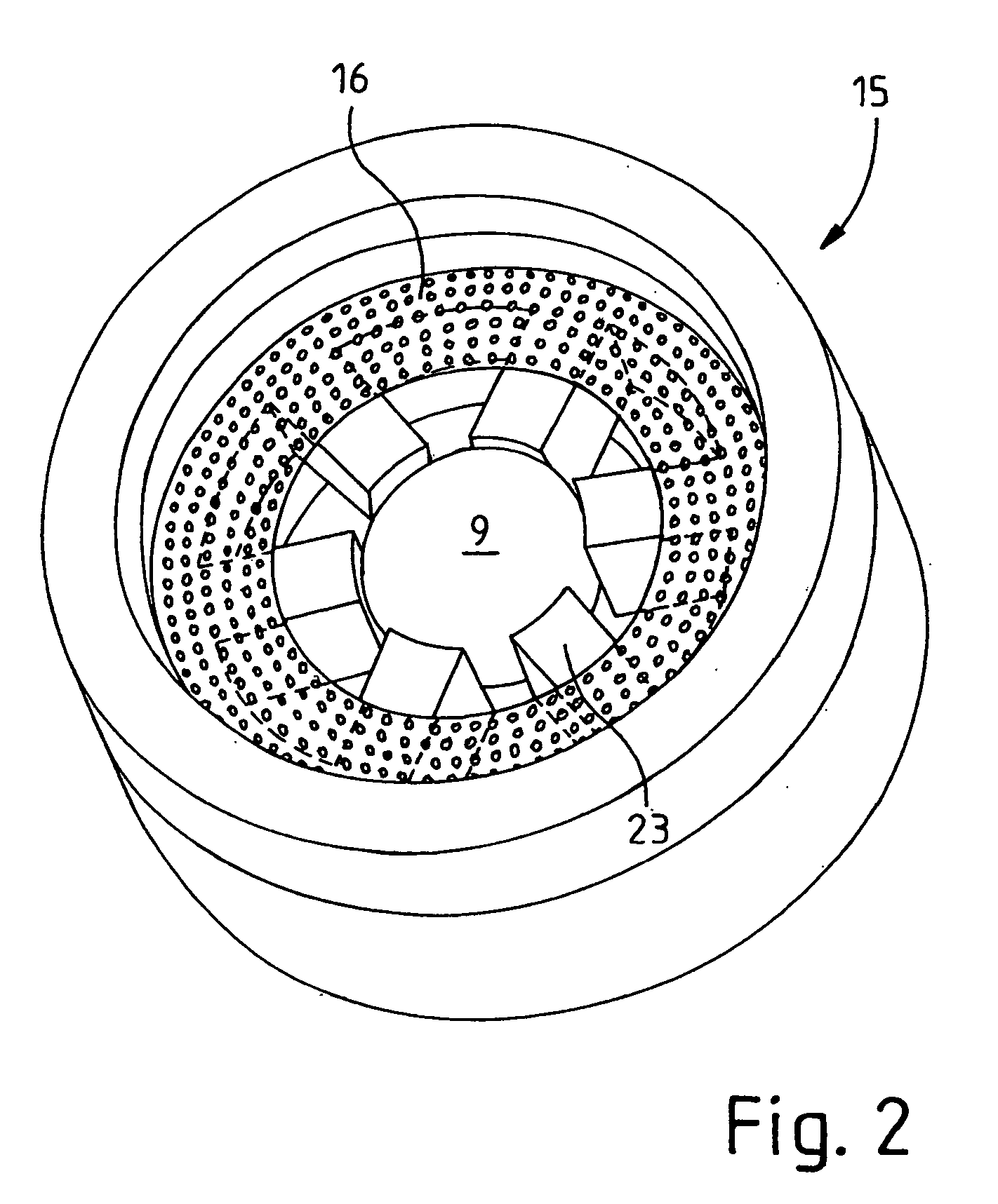
[0049] A guide sleeve 15 according to the invention is inserted between the pole pieces. It simultaneously serves as a spacer element, and thereby precisely defines the ...


PUM


Abstract

An electromagnetic valve is provided that has a compact structural design and has especially low-noise characteristics. This is achieved in a valve with two pole pieces, wherein at least one pole piece is provided with a fluid line and a valve seat, and wherein the fluid line is connected by the valve seat with a valve chamber, in which a valve body is arranged so that it can move between at least two switch settings between the valve seat and at least one other stop surface, which operates at especially low noise levels. This is achieved according to the invention by providing at least one guide piece (15) incorporated in the valve housing to linearly guide the valve body in an axial direction.

Description

CROSS REFERENCE TO RELATED APPLICATIONS [0001] The subject matter of this application is related to U.S. application Ser. No. 10 / 505,354 filed Aug. 19, 2004.STATEMENT REGARDING FEDERALLY SPONSORED RESEARCH OR DEVELOPMENT [0002] Not applicable. INCORPORATION-BY-REFERENCE OF MATERIAL SUBMITTED ON COMPACT DISC [0003] Not applicable. REFERENCE TO A “MICROFICHE APPENDIX”[0004] Not applicable. BACKGROUND OF THE INVENTION [0005] (1) Field of the Invention [0006] The invention relates to an electromagnetic valve having two pole pieces wherein at least one pole piece includes a fluid line and a valve seat in which the fluid line is connected by the valve seat with a valve chamber in which the valve body can move between at least two switch settings. More particularly the invention has at least one guide piece (15) in the valve housing to linearly guide the valve body (9) in an axial direction between switch settings. [0007] (2) Description Of Related Art Including Information Disclosed Under...

Claims


Application Information

Patent Timeline
IPC IPC(8): F16K31/06F16K31/08F25B41/06F25B43/00
CPCF16K31/0606F16K31/0631F16K31/0651F25B2600/2511F16K31/082F25B43/003F25B2500/12F16K31/0662Y10T137/86622F16K31/06
Inventor OTT, HUBERTGRAU, THOMAS
Owner AWECO APPLIANCE SYST
Why Eureka
Try Eureka